We are making a com programmer for avr microcontrollers. Programmers for AVR microcontrollers (USB, COM, LPT). Connecting the Gromov programmer
Hi all. Today I have a new article for you, dedicated to one of the simplest and most popular AVRok programmers - the Gromov programmer - as it is called on the network.
I had been planning this article about the programmer for a long time, but somehow there was no time for it. But now let's get started.
There are two ways to program the AVR controller today:
1) Using a high voltage parallel programmer. This is more of an industrial option, since in this case the controller body is seated in a special socket and high voltage(higher supply voltage) a pre-prepared program is sewn up. After which the controller is soldered into the board at its destination. There is a tangible advantage here - complete control over the entire inside of the controller. And the sewing process is instant.
But what if it turns out that the hardcoded program has an unforgivable bug? So what should you do - the controller is already soldered? Desolder again?
This option is not suitable for amateur radio practice, although it will be useful to have a high-voltage programmer in your stash. In one of the next articles, by the way, it will be very helpful information So do not miss.
2) We will take a different path - and we have an in-circuit programmer at our service. With this method, the controller is installed immediately into the circuit without any intermediate actions. In this case, the program is stitched in-circuit. What does this mean?
It's simple, when developing any device, we provide a programming connector in advance. We install the programming connector directly on the board of our device. This is exactly what I did, there is a connector there, and the connector can be anything, but there is a certain standard for this matter. Typically a ten-pin PLS connector is used, similar to those found on computer motherboards.

So, 5 signals are output to this connector from the controller: mosi, miso, sck, reset, GND. The program will be stitched through these contacts. Moreover, we can do this many times—after all, we don’t have to solder anything. The only thing that needs to be done is that the controller needs to be powered up and running. However, power can also be supplied from the programming connector. Then we will no longer have five signals, but six, but this is not at all difficult. Only here there is a small peculiarity - you need to be careful when placing fuses ( FUSE) before installing the program. If during high-voltage programming an incorrectly wired fuse bit is easily corrected, then during in-circuit programming it will be difficult to correct anything.
A small digression.
Fuses or fuse bits are controller configuration bits. They cannot be removed from the body of the program. Fuse bits are usually set before flashing the program - using a programmer and a flashing program.
Using fuse bits you can change the way the controller clocks. So, if in your circuit the controller is clocked from its internal oscillator, and you set the clocking method from quartz in the fuses, then the circuit will not work. The controller will not start, which means that nothing can be changed. But this is a fixable matter. You just need to solder the required quartz and a couple of capacitors, then everything will work and the program can be further edited and modified.
But there is a fuse bit, by setting which we lose the possibility of in-circuit programming - we need a parallel programmer. So be careful and read the datasheet thoroughly before sewing up fuse bits.
Today there are very, very many varieties of in-circuit programmers, and choosing an acceptable option is not easy. All programmers are divided according to the method of connection to the computer; I know of three: via LPT, COM, USB.
I do not recommend a programmer working through the lpt port in advance, since it is very easy to burn it, and no matter how many circuit solutions were advised to me, I immediately discarded this option. By the way, yes, the lpt port itself was not on my work machine. That's it.
Nowadays, when com and lpt ports are becoming obsolete, the only working option is USB. But there are a number of problems here. As a rule, programmer circuits powered by USB include a microcontroller, which naturally needs to be flashed, and for flashing you need a programmer. This is such a vicious circle. Although recently a USB programmer circuit has appeared on the Internet, which does not require firmware. The scheme is simple, but I haven’t thoroughly understood it, so I won’t talk about it - if you find it very interesting yourself.
We will take a more complicated path - we will start manufacturing the Gromov programmer. This programmer works through a com port, which, unlike lpt, is rare but still found in modern computers. And by the way, if you haven’t found it on the back wall of your computer, this does not mean that it doesn’t exist, since on many motherboards it can be present in the form of pins, pls, you need to read the documentation for motherboard.
Scheme.
The circuitry of the programmer itself is surprisingly simple and I am very sorry that I have not seen it before.

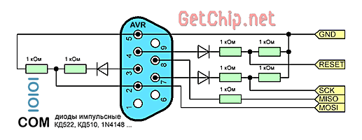
It can even be assembled by hanging it on a knee, but it will still look more solid on the board. For this programmer we need seven resistors of a kilo-ohm each and three low-power diodes. As you know, the voltage from the com port is within 12 V, and the controller operates with a 5-volt voltage. So, a circuit of diodes and resistors will serve us to match the levels. A resistor divider of 12 volts gives us 6 volts, and the remainder of one volt is deposited on the diode - we get 5 volts and this is what we need.
I drew the diagram in the Eagle CAD program, then with a few simple mouse movements, this scarf was born.

You can download the project files from this link.
Her drawing was printed on laser printer and subject to brutality. After all the manipulations, all I had to do was solder the parts and present this creation to your judgment. 🙂


Entrances and exits.
On the left side of the board there are mounting holes for connecting a DB-9F (female) connector known as a COM port connector. it will be connected to our board via wires. The holes for this are indicated on the diagram: DB9/2, DB9/3, DB9/4, DB9/5, DB9/7, DB9/8. The contacts are labeled on the diagram - you won’t miss it :) I would like to add that it is advisable to take the wire no longer than 25 cm. With a longer wire, interference may occur, and as a result, errors when installing the program.
In my version, the power will be supplied from the computer, so for convenience I have displayed the contacts

power supplies PinGND and Pin+5. Then they will be connected to the power connector; in principle, a separate power supply with a voltage of +5 V can be used for this purpose - there will be no problem.
For myself, I saved this connector from an old computer. We solder +5 V to the extreme red wire, and the ground is soldered to the black one. The rest can be bitten out so it doesn't get in the way.
On the right side there are contacts for soldering the ten-pin programming IDC connector. For me it looks like this. Here it comes in conjunction with a DB-9M connector (male).

This entire structure is connected to the programmer board via a DB-9F connector.

Now you can sit back and relax, because we can say that we have completed the task - we have assembled Gromov’s programmer. But we cannot relax for long, because the tests of our creation lie ahead of us. Therefore, in order not to surprise your computer, I advise you to carefully ring everything with a multimeter and check the installation, and only after that proceed to testing our device.
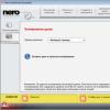
So we have the programmer assembled and lying on the table, waiting. In order to bring to life everything that we have planned, we need control software - the Uniprof Program.
Uniprof program - This is the same software with which our programmer will communicate with the computer. This program was written by an author named Nikolaev, for which an entire army of radio amateurs says to him - THANK YOU. By the way, the program itself can be downloaded from author's website or I have.
We turn off our computer and connect the programmer using a DB-9F connector to the COM port of the computer. I connected the power connector to the power supply of my native computer. At this stage, it is advisable to connect the board of our programmable patient - a board with a controller. I connected an experimental board with an Attiny 45 controller. Well, now a minute of silence. . . press the POWER button system unit computer. We are waiting for our operating system to load.
Let's launch Uniprof. When starting, it cursed a little, displaying a window with the familiar ERROR, saying that there was something wrong with my LPT. . . heh, it’s a bit stupid of course, but we’ll forgive him this time by pointing him on the cross.

At the next stage, the program window did open, but a message appeared stating that the controller did not respond. But we don't panic.

After all, the program is not at all aware of which port our controller is connected to. Here, in addition to the previously mentioned LPT port, there is also a set from COM1 to COM5 to choose from. So by simple search we achieve full identification of our controller.

The controller has been determined, now we need to read it - click on READ.
If the controller is clean, then there should be dashes in the program window, but in my case it turned out differently - the dashes alternated with various hexadecimal numbers. Perhaps the problem was in the long wire connecting the programmer to the computer or to the high performance computer. But in any case, this was cured by checking the “BRAKE” checkbox. The reading time turned out to be slightly longer, but the result was better.

Now it’s time to write the HEX program file to our controller, but we also need to remember to set the correct fuse bits. They are accessed by pressing the button labeled FUSE.

We set everything correctly, having previously studied the datasheet on the desired controller. Important advice: read the fuses and make sure that the fuse bit SPIEN is not set, since setting this fuse will not allow you to use our Gromov programmer for this controller in the future.
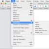
Next, click on the button with an open yellow folder called HEX and select our HEX. 🙂 The program text should be reflected in the Uniprof window. Well, now all that remains is to click on the button with the red arrow called Prog and it’s done.
As you can see, programming the controller using this program is not at all difficult. To become more familiar with it, I recommend reading the help, there you will find answers to your questions.
By the way, read about it, which I soldered and programmed. To do this, the programmer came in handy.
Dear friends, recently a very convenient way to subscribe has appeared, through Email service mailings. So you can leave your email and receive new articles and materials by email. In addition, each subscriber receives a gift that will be useful to every radio amateur, so people subscribe and receive pleasant bonuses, you are welcome.
Well, I think the article will be useful for you and will help you take another step towards mastering microcontrollers. That's all for me, I wish you success and most importantly a good mood!
Best regards, Vladimir Vasiliev.
As an addition, I suggest watching a video on the topic of programming AVR controllers. In order not to miss the next articles, I advise you to subscribe by or by e-mail .
In contact with
Classmates
Most simple programmer for AVR, from a circuit design point of view. The main task of this programmer is to coordinate the levels between the programmable device and the COM port of the computer. The Gromov programmer circuit does not shine with complexity. My signet for this programmer looks like this:
The circuit uses seven 1kOhm resistors. One 330 or 470 ohm resistor (connected to LED).
Three low-power diodes. And one LED. In principle, my circuit can be simplified and the power indicator implemented on an LED can be thrown out. You can download the Gromov programmer diagram in Sprint-Layout format.

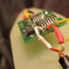
The programmer board should look something like this:
A photo of the finished device was provided by friend eap (Alexander). And all of mine have long gone to university, for which I periodically sculpt interesting toys on microcontrollers.
Connecting the Gromov programmer
The power supply for the programmer must be connected to the jumper near the LED. Power supply 5 volts. The same power will be connected to the power supply of the programmable device. The left block of jumpers is connected to the COM port connector.
In principle, you can simplify everything and solder the cable directly to the board pads. And the cable from the programming connector can also be immediately soldered to the pads of the board. I want to note a small subtlety. The length of the cable from the COM port can be a meter or one and a half, and the length of the cable from the Gromov programmer to the programmable device should not exceed 20 centimeters
The Gromov programmer is a bitbang programmer, so it requires the appropriate software. For example, it can be used in conjunction with Gromov UniProf and avrdude. Disadvantages of the Gromov programmer The main disadvantage is the need to connect to the COM port of the computer. To be honest, this port simply does not exist on all modern laptops, but on desktop computers this port is gradually dying out.
The programming speed through this type of programmer is very low.
Does not work with USB-COM adapters. Doesn't work with
Using a COM port allows you not to be afraid of a short circuit on the programmer; this port is generally very durable and resistant. The simplest elementary base allows us to guarantee that any radio store will have components for it. The simplest electrical diagram allows you to assemble this programmer even on ordinary cardboard and solder everything by surface mounting.
My first set of programmers that I used were the Gromov programmer plus avrdude.
Alternatives
There are a lot of alternatives for the Gromov programmer, here is a small example: AVR910, USBasp, Prottos, USBBit. They all work via USB and can therefore be used when working with modern computers. Also, almost all debugging complexes contain a programmer, for example: STK, BigAVR, Dragon, PinBoard (starting from version 1.1), OrcaBoard (starting from version Rev 2).
Another simple one in terms of manufacturing is the COM programmer. If you use the alternative mode of the Bitbang COM port, there is no need to convert the RS232 COM port interface to SPI, which is necessary for programming. All that remains is to bring the COM port signal levels (-12V, +12V) to the required levels (0, +5V). This is what it does
COM programmer circuit for AVR microcontrollers:
This programmer circuit is quite common and is known as the Gromov programmer. The name came from the author of the program, Gennady Gromov, who proposed such a scheme.
To assemble the Gromov programmer we need the following:
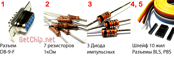
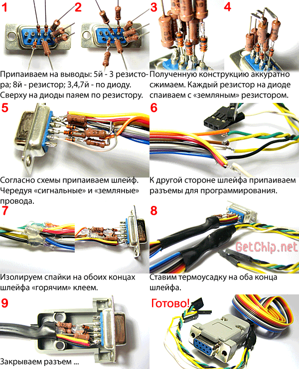
Diodes KD522, KD510, 1N4148 or the like. You can use any resistors you find. You can use an IDE cable as a cable. When connecting a loop, for more stable operation of the programmer, each “signal” wire must alternate with a “ground” wire. This will reduce the level of interference induced in the lines and thereby increase the length of the programming wire. The length of the cable should be within 50 cm. You also need a connector for connecting to the programmable device.
For in-circuit programming, Atmel recommends the following standard connectors:

If you plan to get serious about microcontrollers, make the connectors standard. For one-time programming of the device, I recommend using the programmer (these connectors are used to connect the buttons and LEDs of the computer case to the motherboard - that’s what I took) and the PLS male pins on the board. This makes it possible to simplify the layout of the device board as much as possible, since the pins for the programmer are installed in close proximity to the microcontroller legs. The MOSI, MISO, SCK legs of AVR microcontrollers are always located together, so a triple connector can be used for them. We make separate connections for “ground” - GND and “reset” - Reset.
Assembling a COM programmer is not difficult:
I deliberately do not give printed circuit board for this programmer, since the circuit is simple and fussing with wiring and etching the board simply does not justify itself.
In order for our COM programmer to work needed, to which we will connect the programmer for the microcontroller.
— Since the Bitbang mode is non-standard for a computer’s COM port, malfunctions are possible (although I didn’t experience this). This is especially true for laptops. As a solution to this problem, we can recommend “playing around” with the COM port settings (speed, data bits, flow control options, buffer sizes...).
— It is advisable to connect a separate connector for ground first in order to equalize the ground potentials of the programmable device and the computer. For those who don’t know, if your computer is plugged into a regular outlet, without a grounding contact, then due to the peculiarities of the computer power supply filter, there is always a potential of 110V on the computer case.
Conclusion:
— Gromov’s COM programmer is simple and reliable. I didn’t stop using it even after collecting USB programmer(if any microcontroller stops being programmed with a USB programmer, I will definitely recheck it with the Gromov programmer).
— Since Gromov’s programmer is assembled on passive elements, it does not require power. Moreover, due to parasitic power, the microcontroller can be programmed without connecting a power source to it at all! Although I don’t recommend programming this way, the fact itself is interesting.
— There is a nice bonus for Algorithm Builder users! This programmer can be used for on-chip debugging (software JTAG).
For people who like to design electronic devices, sooner or later the need arises to use microcontrollers in their developments. The use of these devices opens up enormous opportunities for the radio engineer. Microcontrollers are produced by only a few companies; the leaders are Microchip Technology, ATMEL, ARM Limited. A feature of such devices is the need for their firmware. This is what programmers are for. There are many types of these devices, you can buy a branded one, or you can make it yourself. If you choose the second option, it is best to use a ready-made and proven solution, such as the Gromov programmer. The device is quite simple, even a beginner can assemble it.
COM(AVR)-programmer Gromov
The COM programmer is easy to manufacture. Provided that the alternative mode of the “COM” Bitbang port is used, conversion to SPI, which is necessary for programming, becomes unnecessary. All that remains is to coordinate the signal levels in the COM port, from -12V, +12V to 0V and +5V. This is what the programmer circuit for AVR controllers is designed for. The photo below shows Gromov's programmer.
In order to begin assembling the device, we will need:

As you can see, everything is very simple, this is why Gromov’s programmer is valuable.
To operate this device, you need a program and test firmware of the microcontroller.

Using the same principle, you can assemble a usb programmer, but the circuit of such a device is somewhat more complicated.
Of course, the need for a programmer immediately arose. The programmer on the LPT port did not suit me because there is a possibility of burning the computer port. It was possible, of course, to assemble a USB programmer, but it would also need to be flashed with something. Then I came across a diagram programmer Gromov
and it was decided to collect it. They wrote that the programmer works with shells UniProf And avrdude. The scheme itself is very simple:

I downloaded the finished printed circuit board, modified it a little so that I could draw it with a marker, it turned out like this:

All resistors, except for the LED going from the cathode to ground (it has a nominal value of 470 Ohms) are 1 kOhm; there are a total of 7 resistors in the circuit. 1 kohm resistors are installed in order to suppress part of the voltage coming from the COM port from 12 volts to the 5 volts required for the microcontroller. I took the diodes KD522, 3 pieces. The circuit has a power indication on the LED, set in green, Soviet 5 mm in diameter. I had an extension cable in stock COM 9M/9F, just suitable for these purposes, the connector on the back of the cable was cut off by me.

The cable was shielded, which allows you to conveniently position the case with the programmer in any convenient place, as long as the length of the wires is sufficient, whereas in the case of unshielded wiring, if we used only the COM connector, the length is limited to half a meter, otherwise the programmer may not work properly.

Since the conductors coming out of the programmer and going, in my case, to the collet breadboard, on which I will assemble and debug the first devices, are recommended to be no more than 15 - 20 cm long, I made 15 cm long with an ordinary flexible multi-colored mounting wire. It was decided to attach the cable coming from the COM port to the board with a clamp, due to the fact that during operation of the programmer it could break out, since it is quite rigid. The wires coming out of the programmer and going to the microcontroller were also tied together with a wire clamp. The board was etched and tinned:

Read also...
- Cadaques in Spain. My review and photo. Cadaques, Catalonia Cadaques Spain how to get there from Barcelona
- Cart for an online store at the front or Writing modular javascript
- Falling snow on jQuery or html New Year greeting card template
- Where to see what version of Android is installed on an Honor and Huawei phone How to find out the Huawei serial number