Tuning the radio using instruments. How does a radio receiver work? Setting up the radio receiver. Automatic radio tuning function
The high-frequency block contains a converter stage, input and heterodyne circuits. In receivers of the first and highest classes, as well as in the VHF range, there is an amplifier in front of the converter high frequency. Checking and adjusting the high-frequency unit can be divided into three stages: 1) checking local oscillator generation; 2) determining the boundaries of the range, often called range laying; 3) pairing of input and heterodyne circuits.
Laying ranges. The tuning of the receiver to the received station is determined by the tuning of the local oscillator circuits. Input and UHF circuits only increase the sensitivity and selectivity of the receiver. When tuning it to different stations, the local oscillator frequency must always differ from the received frequency by an amount equal to the intermediate one. To ensure constant sensitivity and selectivity over the range, it is desirable that this condition be met at all frequencies in the range. However, this is the frequency ratio across the entire range
is ideal. With one-handed setup, it is difficult to obtain such a pairing. Local oscillator circuits used in broadcast receivers provide precise matching of the settings of the input and local oscillator circuits in each band at only three points. In this case, the deviation from ideal conjugation at other points of the range turns out to be quite acceptable (Fig. 82).
For good sensitivity on the KB range, two precise pairing points are sufficient. The necessary relationships between the frequencies of the input and heterodyne circuits are achieved by complicating the circuit of the latter. The heterodyne circuit, in addition to the usual tuning capacitor C 1 and tuning capacitor C2, includes an additional capacitor SZ, called a mating capacitor (Fig. 83). This capacitor (usually a fixed capacitance with a tolerance of ±5%) is connected in series with a variable capacitor. The inductance of the local oscillator coil is less than the inductance of the input circuit coil.
To correctly determine the boundaries of the range, you must remember the following. The local oscillator frequency at the beginning of each range is mainly affected by a change in the capacitance of the tuning capacitor C 2, and at the end of the range - by a change in the position of the inductor core L and the capacitance of the mating capacitor SZ. The beginning of the range can be considered the maximum frequency to which the receiver can be tuned in a given range.
When starting to set up the local oscillator circuits, you should find out the sequence of settings by range. In some receiver circuits, the CB band loop coils are part of the DV band loop coils. In this case, you need to start tuning with medium wave and then tune to long wave.

Most receivers use a band switching scheme that allows each band to be adjusted independently. Therefore, the configuration sequence can be any.
The range is set using the two-point method, the essence of which is to set the limit of the highest frequency (beginning of the range) using a tuning capacitor, and then the lower frequency (end of the range) with the core of the loop coil (Fig. 84). But when setting the limit of the end of the range, the setting of the beginning of the range is somewhat lost. Therefore, you need to check and adjust the beginning of the range again. This operation is performed until both points in the range are in compliance with the scale.
Pairing of input and heterodyne circuits. The setting is made at two points and checked at the third. The exact coupling frequencies in receivers with an intermediate frequency of 465 kHz for the middle of the range (f cf) and ends (f 1 and f 2) can be determined by the formulas:

The circuits are paired at design points, which for standard broadcasting ranges have the following values

In individual radio models, the pairing frequencies may vary slightly. The lower precision coupling frequency is usually selected 5...10% higher than the minimum frequency of the range, and the upper frequency is 2...5% lower than the maximum. Capacitors with variable capacitance allow you to tune the circuits to exact matching frequencies when turning at angles of 20...30, 65...70 and 135...140°, measured from the position of the minimum capacitance.

To configure tube radio receivers and achieve pairing, the output signal of the generator is connected to the input of the radio receiver (Antenna, Ground sockets) through the all-wave equivalent of the antenna (Fig. 85). Transistor radios that have an internal magnetic antenna are tuned!: using a standard field generator, which is a loop antenna connected to the generator through a non-inductive resistor with a resistance of 80 Ohms.

The decade divider at the end of the generator cable is not connected. The antenna frame is made square with a side of 380 mm from copper wire with a diameter of 4...5 mm. The radio receiver is located at a distance of 1 m from the antenna, and the axis of the ferrite rod should be perpendicular to the plane of the frame (Fig. 86). The magnitude of the field strength in μV/m at a distance of 1 m from the frame is equal to the product of the readings of the generator's smooth and step attenuators.
In the KB band there is no internal magnetic antenna, so the signal from the generator output is fed to the socket external antenna through a capacitor with a capacity of 20...30 pF or to a whip antenna through a decoupling capacitor with a capacity of 6.8...10 pF.
The receiver is tuned on a scale to the highest precise coupling frequency, and the signal generator is adjusted to the maximum voltage at the receiver output. By adjusting the tuning capacitor (trimmer) of the input circuit and gradually reducing the generator voltage, we achieve a maximum increase in the output voltage of the receiver. Thus, pairing is carried out at this point in the range.
Then the receiver and generator are tuned to a lower precise coupling frequency. By rotating the core of the input circuit coil, the maximum voltage is achieved at the output of the receiver. For greater accuracy, this operation is repeated until the maximum voltage at the receiver output is reached. After adjusting the contours at the edges of the range, check the accuracy of the pairing at the middle frequency of the range (third point). To reduce the number of tunings of the generator and receiver, the operations of setting the range and pairing the circuits are often performed simultaneously.
Setting up the LW band. The standard signal generator remains connected to the receiver circuit through the equivalent of an antenna. The generator is set to the lower frequency of the range 160 kHz and output voltage 200...500 µV at a modulation depth of 30...50%. The lower coupling frequency is set on the receiver scale (the rotation angle of the KPI rotor is approximately 160...170°).
The gain control is moved to the maximum gain position, and the band control is moved to the narrow band position. Then, by rotating the core of the heterodyne circuit coils, the maximum voltage is achieved at the output of the receiver. Without changing the frequencies of the generator and receiver, the coils of the UHF circuits (if any) and input circuits are adjusted in the same way until the maximum voltage is obtained at the output of the receiver. At the same time, the generator output voltage is gradually reduced.
Having adjusted the end of the DV range, set the variable capacitor to the position corresponding to the coupling point at the highest frequency of the range (KPI rotation angle 20...30°). The generator frequency is set to 400 kHz, and the output voltage to 200...600 µV. By rotating the trimming capacitors of the circuits, first the local oscillator, and then the UHF and input circuits, the maximum output voltage of the receiver is achieved.
Tuning the circuits at the highest frequency of the range changes the tuning to lowest frequency. To increase the accuracy of the settings, the described process must be repeated in the same sequence 2...3 times. When re-adjusting the rotor, the KPI should be placed in the previous position, i.e. in the one in which the first adjustment was carried out. Then you need to check the accuracy of the pairing in the middle of the range. The frequency of the exact pairing in the middle of the LW range is 280 kHz. By setting this frequency on the generator and receiver scale respectively, the calibration accuracy and sensitivity of the receiver are checked. If there is a dip in the sensitivity of the receiver in the middle of the range, then it is necessary to change the capacitance of the coupling capacitor and repeat the tuning process.
The final stage is checking that the settings are correct. To do this, a test stick, which is an insulating rod (or tube), is inserted into the tuned circuit first with one end and then with the other end, with a ferrite rod fixed at one end and a copper rod at the other. If the adjustment is made correctly, then when any end of the test stick is brought to the circuit coil field, the signal at the receiver output should decrease. Otherwise, one end of the stick will reduce the signal, and the other will increase it. After the LW band is configured, you can similarly configure the MW and HF bands. However, as already noted, on the HF band it is enough to pair at two points: at the lower and upper frequencies of the range. In most radio receivers, the KB range is divided into several subbands. In this case, the exact pairing frequencies have the following values!

Features of setting the HF range. When tuning the HF band, the signal from the generator can be heard in two places on the tuning scale. One signal is the main one, and the second is the so-called mirror signal. This is explained by the fact that on the HF band the mirror signal is suppressed much worse, and therefore it can be confused with the Main signal. Let us explain this with an example. A voltage with a frequency of 12,100 kHz is applied to the receiver input, i.e., the beginning of the HF range. In order to obtain a frequency equal to the intermediate frequency at the output of the frequency converter, i.e. 465 kHz, it is necessary to adjust the local oscillator to a frequency equal to 12,565 kHz. When the local oscillator is tuned to a frequency of 465 kHz below the received signal, i.e. 11,635 kHz, an intermediate frequency voltage is also provided at the output of the converter. Thus, the intermediate frequency in the receiver will be obtained at two frequencies, the local oscillator, one of which is higher than the signal frequency by the amount of the intermediate frequency (correct), and the other lower (incorrect). In percentage terms, the difference between the correct and incorrect local oscillator frequencies is very small.
Therefore, when setting the HF range, you should choose from two local oscillator settings the one that is obtained with a lower capacitance of the circuit capacitor or with a more inverted coil core. The correct setting of the local oscillator is checked at a constant frequency of the generator signal. When increasing the capacitance (or inductance) of the local oscillator circuit, the signal should be heard in one more place on the receiver scale. You can also check the correctness of the local oscillator settings while keeping the receiver settings unchanged. When the frequency of the generator signal changes to a frequency equal to two intermediate ones, i.e., 930 kHz, the signal must also be heard. The higher frequency in this case is called the mirror frequency, and the lower frequency signal is the main one.
Setting up the antenna filter. Setting up the high frequency unit begins with setting up the antenna filter. To do this, the output signal of the generator is connected to the input of the receiver through the equivalent of an antenna. On the frequency scale of the generator, a frequency of 465 kHz and a modulation depth of 30...50% are set. The output voltage of the generator must be such that the output meter connected to monitor the output voltage of the receiver shows a voltage of the order of 0.5... 1 V. Receiver range switch set to the DV position, and the tuning pointer to the frequency of 408 kHz. By rotating the core of the antenna filter circuit, achieve a minimum voltage at the receiver output, while increasing the output voltage of the generator as the signal weakens.
After completing the setup, all adjusted cores of the loop coils and the positions of the magnetic antenna coils must be fixed.
You will need just one chip to build a simple and complete FM receiver that is capable of receiving radio stations in the range of 75-120 MHz. The FM receiver contains a minimum of parts, and its configuration, after assembly, is reduced to a minimum. It also has good sensitivity for receiving VHF FM radio stations.
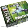
All this thanks to the Philips TDA7000 microcircuit, which can be bought without problems on our favorite Ali Express.
Receiver circuit
Here is the receiver circuit itself. Two more microcircuits were added to it, so that in the end it turned out to be a completely finished device. Let's start looking at the diagram from right to left. The now classic low-frequency amplifier for a small dynamic head is assembled using the LM386 chip. Here, I think, everything is clear. A variable resistor adjusts the volume of the receiver. Next, a 7805 stabilizer is added above, which converts and stabilizes the supply voltage to 5 V. Which is needed to power the microcircuit of the receiver itself. And finally, the receiver itself is built on the TDA7000. Both coils contain 4.5 turns of PEV-2 0.5 wire with a winding diameter of 5 mm. The second coil is wound on a frame with a ferrite trimmer. The receiver is tuned to the frequency using a variable resistor. The voltage from which goes to the varicap, which in turn changes its capacitance.If desired, from varicap and electronic control you can refuse. And the frequency can be tuned either with a tuning core or with a variable capacitor.
FM Receiver Board
I drew the circuit board for the receiver in such a way as not to drill holes in it, but to solder everything from the top, as with SMD components.Placing elements on the board

Used classic LUT technology to produce the board.


I printed it, heated it with an iron, etched it and washed off the toner.


Soldered all the elements.

Receiver setup
After turning it on, if everything is assembled correctly, you should hear hissing in the dynamic head. This means that everything is working fine for now. The whole setup comes down to setting up the circuit and selecting the range for reception. I make adjustments by rotating the coil core. Once the reception range is configured, channels in it can be searched for using a variable resistor.Conclusion
The microcircuit has good sensitivity, and a half-meter piece of wire, instead of an antenna, can pick up a large number of radio stations. The sound is clear, without distortion. This circuit can be used in a simple radio station, instead of a receiver on a supergenerative detector. 1. DETERMINE HOW WE WILL REBUILD THE RECEIVER.So, using reasonable caution, we open the device. Let's see what the frequency setting knob is connected to. This could be a variometer (a metal thing, several centimeters long, usually two or one double, with longitudinal holes into which a pair of cores slides in or out.) This option has often been used before. For now I won’t write about it.() And it could be a plastic cube several centimeters in size (2...3). It contains several capacitors that change their capacity at our whim. (There is also a method of tuning with varicaps. In this case, the tuning control is very similar to the volume control. I have not come across such an option).
2. LET'S FIND A HETERODYNE COIL AND CAPACITORS CONNECTED TO IT.
So, you have KPE! Let's move on. We are looking for copper coils around it (yellow, brown spirals of several turns. Usually they are not even, but crumpled and toppled awry. And this is correct, this is how they are configured.). We can see one, two, three or more coils. Don't be alarmed. Everything is very simple. We turn on your device disassembled (don’t forget to connect a longer antenna) and tune it to any radio station (preferably not the loudest one). After this, we touch with a metal screwdriver or just a finger (contact is not necessary, just pass something near the coil. The reaction of the receiver will be different. The signal may become louder or interference may appear, but the coil that we are looking for will give the strongest effect. It will jump in front of us immediately several stations and the reception will be completely disrupted. This means that this is what a HETERODYNE coil is. The frequency of the local oscillator is determined by a circuit consisting of this very coil and capacitors connected in parallel with it - one of them is located in the control unit and controls the frequency tuning (we use it to detect). different stations), the second is also located in the KPI cube, or rather on its surface. Two or four small screws on the rear surface of the KPI (usually it faces us) are two or four trimming capacitors. Usually these capacitors are used to adjust the local oscillator. consist of two plates that push against each other when the screw rotates. When the top plate is exactly above the bottom, then. capacity maximum.
Touch these screws with a screwdriver. Move them back and forth a few (as little as possible) degrees. You can mark their starting position with a marker to insure against troubles. Which one affects the setting?
Found it? We will need it in the near future. 3. LET'S DETERMINE AGAIN WHERE WE ARE REBUILDING AND ACTING. What range does your receiver have and what is needed. Do we lower the frequency or increase it? To lower the frequency, it is enough to add 1...2 turns to the heterodyne coil. As a rule, it contains 5...10 turns. Take a piece of bare tinned wire (for example, a lead from some long-legged element) and install a small prosthesis. After this build-up, the coil needs to be adjusted. We turn on the receiver and catch some station. No stations? Nonsense, let's take a longer antenna and tweak the setting.
Look, I caught something. What is this. You'll have to wait until they say it or take another receiver and catch the same thing. Look how this station is located. At that end of the range. Need to move even lower? Easily. Let's move the coil turns closer together. Let's catch this station again. Good now? It just catches poorly (you need a long antenna). Right. Now let's find the antenna coil. She's somewhere nearby. Wires from the control unit must be suitable for it. Let's try, turning on the receiver, insert it into it or simply bring some ferrite core to it (you can take the DM choke by removing the winding from it).
Has the reception volume increased? That's right, it's her. To reduce the frequency, it is necessary to increase the coil by 2...3 turns. A piece of stiff copper wire will do. You can simply replace the old coils with new ones containing 20% more turns. The turns of these coils should not lie tightly. By changing the stretch of the coil and bending it, we change the inductance. The tighter the coil is wound and the more turns it has, the
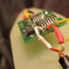
FIGURE 1.
High-frequency part of the VHF-FM radio receiver board. It can be clearly seen that the input circuit trimmer capacitor (CA-P) is set to the minimum capacitance position (unlike the heterodyne trimmer capacitor CG-P).
The accuracy of installation of the rotors of the trimming capacitors is 10 degrees. The local oscillator (LG) coil has a large gap in the winding, which reduces its inductance. This hole appeared during the setup process. Another coil is visible at the top of the photo. This is the input antenna circuit. It is broadband and does not change lanes.
Telescopic antenna
connected precisely to this circuit (via a transition capacitor).
The purpose of this circuit is to remove gross interference at frequencies significantly lower than operating ones.
AND ONE MORE ACTION, SINCE WE ARE ALREADY HERE. Tune to your favorite station, then shorten the antenna to the minimum when interference is already appearing and adjust the IF filter, which you look like a metal square with a purple circle (in the middle left of the photo). Fine tuning of this circuit is very important for clear and loud reception. The slot installation accuracy is 10 degrees. Dear visitors!!! If we compare outdated and modern models of radios, they of course have their differences both in design and in electrical circuits. But the basic principle
radio signal reception
- - not changeable. For
- modern models
radio receivers, only the design itself changes and minor changes are made to the electrical circuits.
As for tuning the radio receiver to the wave, receiving transmissions in the ranges for:

long waves\LW\; medium waves \NE\,- usually carried out using a magnetic antenna. In ranges: — radio reception is received via a telescopic \outdoor\ antenna. Figure 1 shows
appearance
And
graphic designation

receiving antennas:
What is a magnetic antenna? — The magnetic antenna consists of a ferrite rod, and the magnetic antenna coils are wound on separate \isolated\ frames. The ferrite rod of a magnetic antenna for different radios has its own diameter and length. The winding data of the coils, accordingly, also have their own specific number of turns and their own inductance - for each of these magnetic antenna circuits.
As you understand, such concepts in radio engineering as each individual magnetic antenna circuit- usually carried out using a magnetic antenna. In ranges: magnetic antenna coil, - have the same meanings, that is, you can formulate your proposal in one way or another.

In radio receivers, a magnetic antenna for DV and SV is mounted in the upper part. In the photograph, the magnetic antenna looks like an oblong, cylindrical rod made of ferrite.
If each coil \circuit\ of a magnetic antenna has its own inductance, then it is designed to receive separate ranges of radio waves. For example, according to electrical diagram radio receiver You observe that the magnetic antenna consists of five separate circuits \L1, L2, L3, L4, L5\, two of which are necessary for the received range:
- DV \L2\;
- NE \L4\.
Other circuits L1 L3 L5 are communication coils, one of which, say L5, is connected to an external antenna. This explanation is not given specifically for each circuit, because the meaning of the symbols in the circuits may change, but a general concept of a magnetic antenna is given.
Reception-on telescopic antenna

telescopic radio antenna
Depending on the radio receiver circuit, the telescopic \whip antenna\ can be connected either to the input circuits of the long and medium wave ranges through a resistor and a coupling coil, or to the input circuits of the short wave range - through an isolating capacitor. From the taps of the coils of the DV, SV or HF circuits, the signal voltage is supplied to the input of the RF amplifier.
Winding data - antennas
The winding on the circuits is made with a single or double wire. Each circuit has its own inductance. The amount of loop inductance is measured in henry. To independently rewind a circuit, you need to know the winding data of this circuit. That is, you need to know:
- number of turns of wire;
- wire section.
All the necessary technical data for outdated models of radios could be found in reference books. On given time, such literature for modern models of radios is not found.
For example, for receivers:
- Mountaineer-405;
- Giala-404,
— the winding data of the coils coincided with each other. That is, let’s say the communication coil \and there are several of them - in the diagram\ with its designation, it could be replaced from one receiver circuit to another circuit.
A circuit malfunction is often associated with mechanical damage wires \accidentally touching a wire with a screwdriver and so on\. When repairing a circuit \rewinding it\, the number of turns of the old wire is usually taken into account and then the same number of turns are performed with a new wire, where its cross-section is also taken into account.
In this article, we have partially gained an understanding of sound reception by a radio receiver. Follow the section, it will be even more interesting.
Once upon a time there was a Sony radio, when it was sold they said it was Japanese, the price made me believe it, and later I assured everyone that it came from there. Its objective advantage is pure sound. True, there was a small nuance - the FM scale of the 88-108 MHz range, but at the store there was a magician who, for a “small share”, performed a miracle - he filled the scale with many Russian-speaking radio stations. Operated the radio according to full program, but remembering how much was paid for it, they did not throw it or at it. So it was not badly preserved, despite its very respectable age. But the radio broadcasting stations that she caught first diminished, and then there were none left at all.
There is a lot of information on the Internet about setting up sound-reproducing equipment, written competently and in detail. This is a blessing for students of radio engineering universities; they can easily be used instead of notes to prepare for exams, but this information will not help the owner of a sick radio; he is not in the business of increasing his intelligence, but of repairing the receiver. Or throw it away, it’s no longer a shame.

He opened the case and began to disassemble it into its component parts. There are no complaints about either the power supply, which turned out to be super primitive, which is at the bottom left, or the tape drive mechanism of the tape recorder, to the right of it. One produces its 12 V “on the mountain”, and the second regularly pulls the magnetic tape.

And here printed circuit board I wanted to understand a little. To warm up, I checked all electrolytic capacitors for the actual presence of capacity and ESR. It's hard to believe, but everyone turned out to be completely fine. I unsoldered and disassembled the volume control - variable resistor, for example, audit. Once upon a time, a long time ago, he acted a little badly and was, through a medical syringe with a needle, awarded a portion of machine oil. Does it need a supplement? And there was so much oil in it that I could just put it on the frying pan, blot off the excess, and return it to its place. I washed the board on the side of the printed conductors with formic alcohol specially purchased at the pharmacy (they didn’t give anything else), and then, so that there was no white residue left from it, with hot water and shampoo. It turned out not bad, although this method is perceived by ear as a bit wild.

The wire contacts going to the speaker have been soldered. And around the circumference of the speaker I installed a rim - a flexible tube cut lengthwise from a medical dropper. This is so that the metal of the speaker does not rest on the plastic of the housing - it will definitely not worsen the sound characteristics.

And then, very opportunely, I remembered that the master who was modifying the radio tape recorder spoke about some kind of wire spirals. There were several of them on the board, all in the area of the variable capacitor. Partially assembled the device, turned it on, and at the desired range began to touch the copper wires wound in rings with a screwdriver. Two did not respond, and as soon as I touched the third, characteristic sound changes appeared in the dynamics. Found! Bottom one in the photo. I touched it well with tweezers, but it was dangling. I desoldered it, straightened it and wound it again, on a mandrel of a suitable diameter. Soldered it in place. The FM band came to life. At this point I finally got bolder and let’s move the coils with a screwdriver (increase and decrease the gap between them). In response to my actions, the location and number of stations on the scale began to change. But the most convenient for setting were two tweezers. He stretched and squeezed them like an accordion, only gently. See this action clearly in the video.
Video
As a result, I chose a combination of stations that was suitable for myself and optimally located on the scale. The only difficulty is to do everything slowly, otherwise, you know, you want everything faster. Good luck! The simplest option for a possible restoration repair - settings - was shared by Babay iz Barnaula.