The switch is powered from the USB port. USB bus power switches USB powered ethernet switch
Characteristics:
- Delay in appearance of moisture error during hot switching - 1 ms
- Soft start circuit avoids voltage surges
- UL Lab Recognized: Ref No. 205202
- Limiting the output current (no more than 1 A) allows you to protect the power source from short circuits
- Thermal protection
- Maximum static output current - 500 mA
- Miniature SO-8 body
- Input voltage range from 2.7 to 5.5 V
- Open key resistance at 5 V input voltage - no more than 140 mOhm
- Current consumption in standby mode - no more than 1 µA
- Maximum current consumption in operating mode - 200 µA
- Under Voltage Lockout (UVLO)
Application:
- USB hubs for desktop and laptop PCs
- USB monitor hubs
- Self-powered USB hubs
- Powerful USB devices a, requiring current surge limitation
- Power supply switches for general use
Structural scheme:
Pin locations:

General description:
LM3526 - voltage switch USB power supply buses and current limiter. This dual-port device is ideal for use in laptops and laptops.
1 ms error flag setting delay avoids erroneous shutdowns during hot plug-in.
The device has two thermal protection circuits - one for each port. If one of the switches overheats, the other may continue to work.
The LM3526 has an input voltage range of 2.7 to 5.5 V, which allows it to be used as a surge current limiter for 3.3 V USB peripheral devices, as well as devices with self-powered 5.5 V power. The control inputs of the device are compatible with 3.3 V and 5.0 V logic.
The LM3526's small size, low public switch resistance, and 1 ms error flag latency make it ideal for hub and self-powered applications.
Documentation:
| You can get advice and purchase components from the company’s official suppliers |
The switch is powered from USB port
Advances in the design and manufacture of microcircuits not only make it possible to place a complex device on a single chip, but also lead to a significant reduction in the electrical power consumed by this device, which makes it possible to use new methods of power supply. We recently talked on the pages of our magazine about the technology for supplying power to end devices operating in 10Base-T, 100Base-TX and 1000Base-T networks directly via Ethernet cables category CAT5 and higher, which is called PoE (Power over Ethernet). This article will discuss the possibility of powering the switch from a USB port. Remember that the USB port provides external devices power supply with a voltage of 5 V and a current of up to 500 mA.

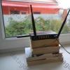
For example, let's take the miniature unmanaged switches MultiCo EW-108R and EW-105T. Both switches are based on highly integrated chips (Realtek RTL8309SB and IC+ IP175C), which are ready-made nine- and five-port switches. These switches can be powered either from external source power supply, as well as from the USB port of the nearest computer or server (the power supply and cable for connecting to the USB port are included in the delivery package).
Switches EW-108R and EW-105T are designed to operate in Ethernet networks of IEEE 802.3 (10Base-T) and IEEE 802.3u (100Base-TX) standards and have 8 and 5 RJ-45 ports, respectively. All ports support automatic detection polarity MDI/MDIX. This eliminates the need for crossover cables or uplink ports. Any port can be connected to a computer or other switch using a straight-through twisted pair cable.
Switching is carried out using Store and forward technology, which ensures packet filtering and removal of damaged ones. The switches' non-blocking & non-head-of-line blocking architecture guarantees wire-speed performance. Flow control is performed using the IEEE 802.3x protocol based on frames in full-duplex mode and backpressure in half-duplex mode. The switches have a built-in MAC address table for 2K entries and 512/768 KB (EW-105T/EW-108R) buffer memory. Auto-negotiation of 100Base-TX or 10Base-T speeds and full-duplex/half-duplex connection mode makes installing the switch into an existing Ethernet network very simple.
The switches have a power indicator and port indicators (one for each port) to help you determine if there is a connection and network activity. Durable metal housings guarantee good cooling and long service life. The dimensions of the case are practically determined by the dimensions of the interface connectors and are 79S62S20 (EW-105T) and 94S62S20 (EW-108R) mm. Thanks to passive cooling The switches operate completely silently.
Compact dimensions and low power consumption open up wide possibilities for choosing where to place switches (for example, they can be hidden in cable channel). Using the included self-adhesive magnetic rubber feet, the switch can be easily attached to any steel surface.
To check operation, a workstation based on Intel processor Pentium 4 3.0 GHz, equipped with integrated motherboard gigabit network adapter Marvel Yukon Gigabit Ethernet 10Base-T/100Base-TX /1000Base-T Adapter, which operated in 100Base-TX mode.
An operating system was installed at the workstations Windows system XP Professional SP1.
To generate network traffic over the TCP protocol and measure performance, the NetIQ Chariot 5.0 software package with the High_Performance_Throughtput.scr load file was used.
The test was performed with a gradual increase in the load on the switch. At the first stage, transmission was switched on between the first and second stations, then between the second and third, and so on, until the transfer was switched on between the last (fifth or eighth) and first stations. As a result, at the last stage, all stations and, accordingly, all ports of the switch operated in duplex mode. The test results (Figures 1 and 2) show that the switches can easily handle the load. Performing the test with different power supplies (from an external power supply or from a USB port) did not reveal any differences in the operation of the switches.


The editors express gratitude to MultiCo ( www.multico.com.ru ) for providing EW-105T and EW-108R switches for testing.
Development network technologies in the last decade has led to the fact that network adapters are installed in almost every new system unit during assembly, and everyone, young and old, dreams of the Internet. Once I was driving home from work and heard two girls talking to each other: “Let’s go to my place and surf the Internet...” In general, it is not clear how our grandparents managed without computers in general and networks in particular.
This rapid development has led to a significant reduction in the price of network hardware, an increase in data transfer speed and, naturally, the emergence of a large number of new standards. Thus, switches began to quickly displace hubs from the market, attracting them with their not very high price and properties that hubs do not have. For local networks, unmanaged switches have become especially popular. They are characterized by simplified element base, the presence of only basic functions, small size and, as a result, low price. Such devices are usually called “mini-switches”.
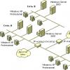
Most existing local networks are built on Ethernet technology. Networks built using this technology operate in accordance with the principles of CSMA/CD (Carrier Sense Multiple Access/Collision Detection - multiple access with carrier sensing and collision detection), which complies with the IEEE 802.3 Ethernet specification. In an Ethernet network, all workstations can receive data simultaneously, but only one of them can transmit data to the common bus at a given time. Thus, as the number of computers on the network increases, its throughput decreases.
Hubs are devices that implement Ethernet technology. All clients connected to the hub ports operate in half-duplex mode (they can only receive or only transmit data at the current time). All data frames received by the hub from any port are relayed to all other ports, thus the common bus - the main disadvantage of Ethernet - is preserved.
Networks built using only hubs are very sensitive to the number of running clients. In such networks, the load factor should not exceed 40%. The scalability of such networks also suffers greatly (all because of the same common bus). In addition, there are restrictions on the maximum distance of clients from each other and restrictions on the maximum number of hubs between them.
The solution is to use switches. They are more advanced devices compared to hubs. Their main difference is the ability to analyze the addresses of the sender and recipient of a data packet and relay the packet only to the port to which the recipient is connected. Thus, switches change the access mode to the transmission medium, divide the network into several (corresponding to the number of ports on the device) collision segments and provide each network node with a virtual dedicated channel bandwidth.
During operation, the switch is able to “learn” - passively observing the traffic passing through it, it builds an address table (table MAC addresses), according to which it will transmit data (frames) not to all its ports, but only to the destination port.
The recipient address of a frame arriving at the switch port is looked up in the address table. If it is present there (and the destination is not on the same port), the switch sends the frame to the corresponding destination port. This process is called forwarding. If the recipient is on the same port from which the frame came, then such a frame is destroyed. This is called filtering. If the address of the frame recipient is not in the address table, then the frame is sent to all ports. That is, in the latter situation, the switch acts as a hub.
Most modern switches can operate in both 10Mbits (Megabits per second) Ethernet and 100Mbits Fast Ethernet modes. In half and full duplex mode. Usually there is a function for auto-detecting the speed of the port.
In half-duplex mode, both twisted pairs are used (one of them is called TX - used for transmission, the second - RX - for reception), but data reception and transmission cannot occur at the same time - either only reception or only transmission. In this case, collisions may occur even if the workstation is directly connected to the hub. This happens when the switch and workstation simultaneously want to transfer data. A collision is determined by the presence of a signal in the RX pair at the time of an attempt to transmit in the TX pair.
The switch can regulate the data flow in this mode using two methods - the backpressure method and the aggressive behavior of the switch port. The need to regulate the flow arises in a situation where it is necessary to unload the port buffer, which is overflowing with data, but this cannot be done, since data arrives at the port from outside.
In the first case, if it is necessary to suppress port activity, the switch generates jam sequences to it. Collisions occur on the port, which leads to the cessation of traffic from it.
In the second case (it is now practically not used), when accessing the transmission medium on this port, the switch does not withstand the pause provided by the standard. As a result, the switch takes exclusive control of the bus and transmits its data to the workstation (or other device).
Full duplex mode allows for simultaneous reception and transmission of data over both twisted pairs. If an end device (another switch or workstation) is connected to the switch port, then collisions cannot occur. But nothing prevents congestion (port buffer overflow) from occurring, so traffic regulation mechanisms are also provided here.
For this purpose, IEEE 802.3x - Advanced Flow Control technology is used. The switch inserts “Suspend transmission” and “Continue transmission” service frames into the data stream. The network adapter, of course, must also support this standard.
The performance of miniswitches, one of which is presented below, is influenced by several key parameters. The most important are forwarding speed, filtering speed, throughput, frame transmission delay time, switching type, buffer memory size and address table size.
Even these parameters are not always indicated in the documentation for switches. Therefore, in the absence of such data in the documentation, we will assume that when transmitting frames of minimum length, the forwarding speed coincides with the protocol speed and is 148800 packets for 100Mbits and 14880 for 10Mbits. For larger frames, which are usually the main component of traffic, these speeds will be lower.
Mini switches typically implement only one type of switching. As a rule, this is switching with intermediate buffering. The entire frame is first received into the buffer, and only then is it analyzed check sum(for frame distortion) and a header for the recipient's address. The frame is then sent to the output port. This method is not the fastest, but the switch does not allow erroneous (distorted) frames to pass through.
Testing methodology
Testing of mini-switches includes both physical testing in real network, as well as subjective assessments of the functionality and design of the switch.
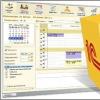
For the first part, the IOMeter utility developed by the company was used. Unfortunately, the company does not support this program, but simply posted it on its own “as is”.
IOMeter allows you to generate traffic from given parameters, and also collect statistics on it. You can set many parameters for traffic, but we were interested in generating traffic of maximum intensity, so we chose:
- transmission type - 100% serial
- type of transmission - 100% recording
- data block size - 64KB (this is not the size of the Ethernet packet, but the data block that the program operates on)
- The delay time for packet transmission is minimal.
To measure data transfer speeds, we used system utility operating system"Performance Monitor".
For testing, a peer-to-peer the local network Fast Ethernet from 5 computers. Each one is equipped with Windows XP Professional OS and Intel Express 100 network adapters. The default QoS - load balancing - has been removed from the network protocols (it is designed to equalize traffic and may cause a decrease in the speed of data reception/transmission).
Network card settings:
- 802.1p QoS packet tagging (priority frame processing) - disabled.
- Link Speed & Duplex (transmission speed and the presence of full duplex) - changed depending on the specific test.
Let's move on to the description of the tests.
- 1. Maximum switch load.
- All 5 workstations are involved. (With a five-port switch).
- Transfer speed - 100Mbits, Full Duplex.
- We set the traffic transmission mode “all to all” - each workstation transmits and receives data from the other 4 stations.
- 2. Data transfer between two ports in the absence of traffic on the others (ideal case).
- 2.1 One-way transmission from 100Mbits Full Duplex to 100Mbits Full Duplex port.
- 2.2 Two-way transmission between 100Mbits Full Duplex and 100Mbits Full Duplex ports.
- 3. Read data from one port to all others.
Let's emulate a "server and many clients" situation. - 4. Data transfer between 10Mbits and 100Mbits segments.
Here we find out the quality of switching between two segments with different transmission rates and duplex parameters.- 4.1 One-way transmission from 10Mbits Full Duplex segment to 100Mbits Full Duplex.
We emulate a connection on one side of a client with a 10Mbits network adapter and a 100Mbits adapter or 100Mbits switch on the other side. - 4.2 One-way transmission from 10Mbits Half Duplex segment to 100Mbits Full Duplex.
We emulate the connection of a 10Mbits hub on one side and a 100Mbits adapter or 100Mbits hub on the other side.
Transferring data from a low-speed port to a high-speed port usually does not cause problems. - 4.3 One-way transmission from 100Mbits Full Duplex segment to 10Mbits Full Duplex.
- 4.4 One-way transmission from 100Mbits Full Duplex segment to 10Mbits Half Duplex.
These two tests are relatively difficult modes for the hub, since it has to equalize (lower) the data transfer rate from the 100Mbit port to the 10Mbit port. - 4.5 Two-way transmission between 100Mbits Full Duplex and 10Mbits Full Duplex segment.
- 4.6 Two-way transmission between 100Mbits Full Duplex and 10Mbits Half Duplex segment.
- 4.1 One-way transmission from 10Mbits Full Duplex segment to 100Mbits Full Duplex.
- 5. Let's not forget about the 100Mbits hubs that can be connected to the switch.
- Data transfer between 100Mbits hub and client.
- 5.1 One-way transmission from 100Mbits Half Duplex to 100Mbits Full Duplex port.
- 5.2 One-way transmission from 100Mbits Full Duplex to 100Mbits Half Duplex port.
- 5.3 Two-way transmission between 100Mbits Full Duplex and 100Mbits Half Duplex ports.
Transfer data between 100Mbits hub and 10Mbits hub.
- 5.4 One-way transmission from 100Mbits Half Duplex to 10Mbits Half Duplex port.
- 5.5 One-way transmission from 10Mbits Half Duplex to 100Mbits Half Duplex port.
- 5.6 Two-way transmission between 100Mbits Half Duplex and 10Mbits Half Duplex ports.
Data transfer between 100Mbits hub and 10Mbits client.
- 5.7 One-way transmission from 100Mbits Half Duplex to 10Mbits Full Duplex port.
- 5.8 One-way transmission from 10Mbits Full Duplex to 100Mbits Half Duplex port.
- 5.9 Two-way transmission between 10Mbits Full Duplex and 100Mbits Half Duplex ports.
- 6. Data transfer between two 10Mbits ports. Of course, it usually makes no sense to connect 10Mbits network adapters to a 100Mbits port at today's prices for Fast Ethernet cards, but nevertheless this happens. Well, installing switches in the center of a star of hubs or simply combining two 10Mbits segments is common practice. Therefore, we will consider this possibility.
- 6.1 One-way transmission from 10Mbits Full Duplex to a 10Mbits Full Duplex port.
- 6.2 Two-way transmission between 10Mbits Full Duplex and 10Mbits Full Duplex ports.
Emulation of two workstations with 10Mbits network adapters or data transfer between two 10 megabit hubs.
We simulate the connection of two hubs to the switch ports.
- 6.3 One-way transmission from 10Mbits Half Duplex to 10Mbits Half Duplex port.
- 6.4 Two-way transmission between 10Mbits Half Duplex and 10Mbits Half Duplex ports
We simulate the connection of hubs to one of the switch ports and a 10Mbits network adapter to the other.
- 6.5 One-way transmission from 10Mbits Half Duplex to 10Mbits Full Duplex port.
- 6.6 One-way transmission from a 10Mbits Full Duplex segment to a 10Mbits Half Duplex port.
- 6.7 Two-way transmission between 10Mbits Half Duplex and 10Mbits Full Duplex ports.
By functionality we mean, first of all, the “information content” of the switch. Since for unmanaged switches the only way to transmit information and statistics about their operation is LED indicators, then we evaluate their number and ability to reflect maximum information about the port - operating speed, presence of full duplex, collision detection, data transmission indication, information about emergency shutdown of the port. And also a power indicator. We include the presence of an “uplink” port in the same category.
The design includes the size of the switch (relative to the number of its ports), the possibility of wall mounting, and, well, its appearance.
Naturally, this is not the final version of the technique; it will be supplemented with polishing. Express any suggestions you have to .
Testing
Based on the above methodology, let's look at the company's mini-switch. - GS-SW005.
Apparently, this is one of the company's first products in this area. But this does not explain why there is no information on it on the company’s English website. True, it is on the Japanese mirror (apparently, only the main characteristics of the switch are given there), but not everyone knows Japanese...
The delivery set includes the switch itself (its body is completely metal), a small book-tape with documentation on it, and an adapter cable for powering the device via a USB port. Judging by the documentation, there should also be a power adapter, and a USB adapter should be included as a bonus, but in our case there was no adapter. This adapter has a big disadvantage - its length is only 22cm not counting the connectors, which allows you to install the device only from above system unit(the cable is no longer long enough for installation on the floor/table) or on the side of the case.

Also included was a mysterious strip with 4 flat magnets on an adhesive paper backing. It turned out that they are intended for attaching the device to the side wall of the system unit. This assumption was confirmed by careful study of the instructions. The test showed that they hold quite tightly.

The switch itself is very small, fits in the palm of your hand. For comparison - a little higher, in the main photo next to it there is a coin worth 2 rubles. But heavy, relative to its size, due to the metal body.
On the front of the switch there is a power indicator and 5 pairs of indicators showing the status of the ports, two per port, respectively. The indicators are green, single color.
When the top one is lit, something is connected to the port. Flickering - data transmission or reception. The lower one is lit - the presence of full duplex. Blinking indicates the presence of a collision in half-duplex operating mode. There is no port emergency shutdown indication.

On the side there is a power connector for connecting a network adapter or an adapter for USB power. Fork USB adapter It does not hold tightly and can fly out during careless movement due to the short length of this cable (for example, when moving the switch). Unfortunately, there are no holes on the cover for wall mounting of the device; mounting is only possible on metal case computer with the included magnets.

There are 5 port connectors on the back, one of which is an uplink. Both unshielded and shielded twisted pair cables can be connected to the ports.

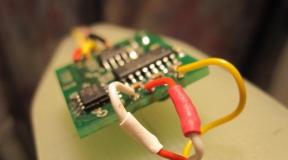
Now let's see what's inside:
The device is assembled on a KS8995 microprocessor from KENDIN Communications. It is the main node of the device and supports 5 ports for twisted pair or optics. In this case, twisted pair ports were used.

The established operating mode of the microprocessor is a switch with five independent ports. Integrated SRAM is used as a buffer memory, the volume is 32Kx32. Bandwidth his internal memory(and accordingly the switch) - 1.4Gbps.
Switch characteristics:
- Number of ports - 5
- Supports IEEE 802.3 (10Base-T - Ethernet 10Mbits) and IEE 802.3u (100Base-TX - Fast Ethernet 100Mbits)
- Supports half- and full-duplex operation in both cases
- Auto-detection of operating speed and duplex mode
- Store and Forward support (switching with intermediate buffering)
- Full Duplex 802.3x Flow Control support
- Half Duplex Back Pressure Flow Control support
- N-Way auto negotiation support
- BroadCast Storm Protection
- Number of memorized MAC addresses - 1K
- Power type - +6VDC/500mA, optional - +5VDC from PS/2 connector
- Dimensions (W/D/H) - 82mm × 66mm × 20mm
- Operating temperatures - 0–40°С
- Operating humidity - 5–90%
- Price at the time of writing - $35
- Price per port - 7$
Test results.
Pivot table.
Data going only in one direction (half duplex) through the port is counted, unless otherwise specified. Speed is calculated in kilobytes (not kilobits!). Periodic change speed (on average about five minutes between the upper and lower values) is reflected by the upper and lower limits separated by a hyphen (for example, 10--100). In this case, usually the maximum value from the first client corresponded to the minimum value from the second.
| test | clients | first mode, Mbits | duplex first | first transfer rate, KByte/sec | transmission direction | second mode, Mbits | duplex second | transfer rate of the second, KByte/sec |
| 1 | 5 | 100 | Full | 10350 | ||||
| 2,1 | 2 | 100 | Full | 12300 | --> | 100 | Full | |
| 2,2 | 2 | 100 | Full | 12100 | 100 | Full | 12100 | |
| 3 | 4+1 | 100 | Full | 12100 | --> | 4×100 | Full | |
| 4,1 | 2 | 10 | Full | 980 | --> | 100 | Full | |
| 4,2 | 2 | 10 | Half | 1190 | --> | 100 | Full | |
| 4,3 | 2 | 100 | Full | 320–400 | --> | 10 | Full | |
| 4,4 | 2 | 100 | Full | 1040 | --> | 10 | Half | |
| 4,5 | 2 | 100 | Full | 440–520 | 10 | Full | 180–250 | |
| 4,6 | 2 | 100 | Full | 270 | 10 | Half | 920 | |
| 5,1 | 2 | 100 | Half | 1800–2150 | --> | 100 | Full | |
| 5,2 | 2 | 100 | Full | 6050–6300 | --> | 100 | Half | |
| 5,3 | 2 | 100 | Half | 850–2600 | 100 | Full | 980–1620 | |
| 5,4 | 2 | 100 | Half | 320–450 | --> | 10 | Half | |
| 5,5 | 2 | 10 | Half | 1160 | --> | 100 | Half | |
| 5,6 | 2 | 100 | Half | 70 | 10 | Half | 1150 | |
| 5,7 | 2 | 100 | Half | 240–270 | --> | 10 | Full | |
| 5,8 | 2 | 10 | Full | 1170 | --> | 100 | Half | |
| 5,9 | 2 | 100 | Half | 110–200 | 10 | Full | 600–610 | |
| 6,1 | 2 | 10 | Full | 50 | --> | 10 | Full | |
| 6,2 | 2 | 10 | Half | 50--150 | 10 | Full | 50–150 | |
| 6,3 | 2 | 10 | Half | 1030 | --> | 10 | Half | |
| 6,4 | 2 | 10 | Half | 515 | 10 | Half | 515 | |
| 6,5 | 2 | 10 | Half | 550–580 | --> | 10 | Full | |
| 6,6 | 2 | 10 | Half | 350 | --> | 10 | Full | |
| 6,7 | 2 | 10 | Half | 380 | 10 | Full | 140 |
It is clearly seen that the switch copes perfectly with switching purely 100Mbits full-duplex clients. But with the advent of the half-duplex 100Mbits mode, the data transfer speed drops significantly, although it still remains at an acceptable level. This is when transmitting data in one direction.
When simultaneously transferring data between 100Mbits segments with different duplex parameters, a picture incomprehensible for 100Mbits is observed - transfer to a full-duplex segment ranges from one to one and a half megabytes, and in the opposite direction - from one and a half to two and a half.
When switching segments with different speeds (10Mbits on one side and 100Mbits on the other), high speed is observed only during data transfer from a low-speed segment to a high-speed one. In the opposite direction, the speed drops simply catastrophically.
But what was most disappointing was the operation of the switch in a purely 10bits environment with full duplex. The work speed was very slow. Especially when switching two full-duplex 10Mbits clients with each other, data was transferred at a speed of 50–150Kb. Thus, when connecting 10Mbit workstations to this switch, it is better to force, if possible, to disable full duplex on the network adapter. In half-duplex 10Mbits mode, the operation of the device did not cause any complaints.
In terms of functionality, we can say the following: the indicators reflect all possible states of the port, except for its emergency shutdown (the latter is a minus). The indicators are really small and located close to each other, but this follows from the physical dimensions of the device.
The uplink port is present, but with some reservations. There is no uplink/normal switch button. That is, to use this port to connect a workstation, you need a crossover cable. This is stated in the documentation and most likely this is a property of this device, again resulting from its minimal size and low price.
Conclusions.
Gigabyte's GS-SW005 switch is aimed at the lower end of the market - cheap but functional devices (functionality here refers to the properties of the switch as such). Small size and the ability to be powered from a computer USB port, as well as low power consumption allow you to carry and use it even with a laptop. The main area of application is the rapid networking of several computers equipped with 100Mbits network adapters. The switch is not suitable as a switching device for several heterogeneous Ethernet networks and workstations.
- low price per port
- ability to receive power from a computer
- miniature sizes
- high-speed switching in 100Mbits mode.
- low speed when switching segments of different speeds.
- low speed when working with 10Mbits ports in full duplex mode.
I express special gratitude to the head of the testing laboratory of the publishing house "" Sergei Pakhomov for their help and comprehensive advice in preparing the material.
I also thank Andrey Vorobyov for providing photographic and computer equipment and moral support.
1 0G USB-C Gen 2Switch ATEN US3342 allows you to work with two USB-C computers as with one workstation using shared USB peripherals
The 10G USB-C Gen 2 Sharing Switch US3342 with Power Pass-through is specially designed by ATEN for programmers, developers, system administrators, PC repair specialists and content creators to improve the efficiency of dual-system operations.
Peripheral 10G USB-C Gen 2 Switch US3342
US3342 –Share devices between two USB-C computers
No more hassle of plugging and unplugging. Connect yours USB-C laptops to US3342 and start a joint . Use just one set of keyboard and mouse to seamlessly control two systems and share data and multiple USB devices without having to plug and unplug or configure complex network settings server/client.

US3342 –Manage two computers as one
Switching between computers has never been so easy and intuitive. Mouse switching allows you to easily move the mouse cursor across the screen border and onto the target computer to switch controls without pressing a button. Less time switching, more time creating and producing.

US3342 –Ultra-fast work
The US3342 creates a direct link between two computers with transfer speeds of up to 10 Gbps. By using public access to the clipboard, you can copy and paste or drag and drop files, images and texts directly from each other without using a storage device as an intermediate step with double the transfer time. Ultra-fast 10Gbps transfer speed allows you to operate at unprecedented speeds, up to 20 times faster than USB 2.0.

Transit source USB-C power supply 3.0W 85W power charges one of your laptops and also provides enough power for power-hungry devices such as external hard disks and gaming devices. You can use your favorite keyboard and mouse to work and play, even with powerful RGB gaming hardware.

US3342:Two systems as one computing environment – Limitless switching and transfer
With the US3342, your computers can run smoothly and communicate seamlessly, whether they are Windows to OS X, OS X to OS X, or Windows to Windows.

The US3342 10G USB-C Switch enables you to create simplified, productive workspaces for any desktop environment.