MD terminator 3 two-tone. DIY metal detector (circuit, printed circuit board, principle of operation). Assembling the circuit and selecting parts
Metal detector Terminator 3
For a long period of time, this unit has been one of the best among homemade devices for detecting metal. Over the years, this device has been modernized more than once, resulting in new modifications of the metal detector. With this device you can only find gold or non-ferrous metals - this will depend on the selected setting. Making a Terminator 3 metal detector with your own hands will not cause any difficulties at all, but to do this you must follow the instructions below.
Terminator 3 diagram
Terminator 3 parts list

How to make a Terminator 3 circuit board with your own hands
The assembly of the circuit of the future device is carried out on a printed circuit board; you can make it yourself at home, for this you need:
1.Print the image of the board on glossy paper; during printing, it is necessary to “adjust” the image to the required dimensions. After printing, you need to get rid of excess edges, but so that there is 10 millimeters left on each side. Next, you need to purchase foil PCB that will match the size of the board. It should also have a margin of 10 millimeters on all sides. The textolite must be cleaned with sandpaper until it shines.
2. Place the image of the circuit on the PCB, secure it with any durable material (good tape or superglue) along the edges that were left. Next, you should use a screw or core to mark the places where any holes are located, after which you should peel off the print from the PCB. These holes must be drilled taking full account of the image on the circuit board. For drilling, you should use a drill that has an appropriate diameter of 0.5 - 0.7 millimeters for resistors and 0.9 for power transistors and wires. Next, you need to reduce the textolite to the required size. For these purposes, you can use a hacksaw or other tool.
3. Very carefully, focusing on the installation diagram, apply the tracks using varnish or a permanent marker and wait until they dry completely.
4.At this stage, the board is etched. For this purpose, it is necessary to mix 10 milliliters of a 3% peroxide solution, 30 grams of citric acid and 5 grams of kitchen salt in a container, and stir everything until the ingredients are completely dissolved. Next, you should place the textolite in the reservoir with the resulting liquid. Then you have to wait until the copper coating on the board is completely dissolved. In order for the above process to speed up, you should warm up this solution a little, stirring constantly.
5.Once the etching is complete, the applied strips must be removed with acetone. Next, you need to wash the board from any remaining solution with water. You can use alcohol for this purpose. The tracks must be tinned with solder carefully so that the holes for the parts are not soldered.
The board made in this way is ready for installing parts.

Assembling the circuit and preparing the necessary parts
Based on the diagram of the Terminator 3 metal detector and the drawing of the circuit board, it is possible to begin assembling the board.
A diagram of the unit can be found on the World Wide Web, as well as a list of necessary parts. In the diagram, some elements can be indicated by “asterisks” and they can be selected through experiments so that the resulting device turns out to be improved. But for the first assembly you must strictly adhere to this scheme. Experiments can be continued at the stage of setting up the metal detector.
To begin soldering parts, you must first connect the jumpers that are located near the radio components. For this purpose, it is necessary to use varnished or insulated wire with a small cross-section.
The smallest elements must be soldered near the tracks, after which it is necessary to solder the sockets intended for microcircuits and other elements that are available. The wires necessary to attach the regulation and control panels to the metal detector, mode changes, power supplies, and light/sound indicators must be routed out. You also need to find caps for the adjustment resistors. At the last stage, you need to remove the connector that will be needed for the sensor wires.
To check if everything is working, you will need to connect a 9V battery. If the connection was correct, the LED will light up and go out. The same should happen when the device is turned off. If you touch the connector where the sensor is supposed to be installed, the sound will disappear for a while.
It is also necessary to carefully check all available control voltages that are in the circuit. For this purpose, it is necessary to enable a mode that assumes a constant voltage, which should be 20V. With a plus probe, it is necessary to measure the existing voltage that is present at the points of this circuit, and the minus probe must be applied to the minus.
To make the case, a plastic box of the required size is used. It must be fixed to the device rod. Buttons and controls will need to be signed in accordance with the functionality assigned to them.
Making a coil for Terminator 3
An important component of all metal detectors are search sensors. In this case, it consists of two coils located in the housing. It is through their use that metal objects will be found.
To assemble the search coil for the Terminator 3 metal detector, the following parts are required:
·epoxy adhesive;
adhesive tape;
·foil;
·varnish;
threads
· frame ;
· a special wire to connect the circuit and the sensor;
·PETV winding wire having a cross-sectional size of 0.4 millimeters;

The first priority is that you will need to make a coil housing for the sensor. It is better to purchase a factory case, or one molded from ABS plastic, rather than try to produce it yourself. You can also do it yourself, but it will take a lot of time and labor. The advantages of the purchased housing are that the recess for the coils is of the required size. The rod can be made from any material with dielectric properties.
Next you need to wind the windings. The diameter should be selected based on the body - 20 centimeters. They need to be wound on a product that has a round shape, which has a similar diameter. The winding must be done clockwise. Thirty turns should be made. Get four outputs. All winding sections will need to be connected as tightly as possible with threads and varnished. At the end of drying, you need to wrap the turns using electrical tape, after which the process should be completed by wrapping it with foil. There is no need to close the circle of foil; you need to leave 1 cm without it. The wires will need to be connected and brought out to the foil. After completing all actions, the TX coil should be re-wound with electrical tape.
The second coil will need to be created in a similar way, but the diameter should be half as large. It is necessary to wind with forty-eight turns. Also, as before, you should connect two wires to the external winding.
To wind the middle coil, you need to make twenty turns in a counterclockwise direction. One should take into account the fact that it will need to be placed in a groove, next to the external winding coil. CX does not need to be additionally varnished or insulated.
At the end of the work you will have three coils available.

Setting up the Terminator 3 metal detector
In order to assemble a metal detector, you need to use a device called an oscilloscope. An important role is played by the complete absence of metal objects with this device. To set up the Terminator 3 metal detector you will need to perform the following steps:
1.
align the frequency of the coils;
2.
balance the coils.
Initially, a coil with an external winding is connected. Next, you should turn on the device. The minus probe should be applied to the minus located on the board, and the plus probe should be applied to one of the terminals located on the coil. Next, you should measure the frequency. Similar manipulations should also be carried out with the external coil. Its frequency should be 100 Hz less than the same data on TX.
The next step is to lay all the windings in one housing. Next, you will need to connect both coils with a reserve. You should connect the minus of the oscilloscope to the minus located on the board, and the plus to the terminal of capacitor C5 and RX. The time on the oscilloscope must be set to 10 ms, and the voltage must be set to 1V.
When setting up the Terminator 3 metal detector, you need to achieve a minimum amplitude. For this reason, it is necessary to solder the output of the middle coil in order to reduce the existing number of turns. When the desired results have been achieved, it is necessary to switch the regulator to the lowest value. Similar actions should be repeated until the smallest amplitude is achieved.
It is now possible to fill part of the existing circuit with epoxy glue, but please note that the CX and RX adjustment loop must be left free.
How to prepare Terminator 3 for work

In order to make the settings, you should set the switch to a mode that allows you to detect metals. The ground balance regulator will need to be set to 40-50 kOhm. Discrimination will need to be set to zero. Next, you will need to bring an object made of non-ferrous metal and ferrite to the Terminator 3 metal detector. If the reaction to ferrite is the appearance of two signals, and to metal there is only one, then you did everything right.
Hello to all comrades, today we will try to figure out what kind of metal detector is the Terminator? Have you probably heard of such a device? In particular, one of the popular models is the third. A friend of mine, whom we met on the Internet thanks to our hobby, has a “Therma” and this is what he told me about this device.
There are plenty of photos on the Internet, all different modifications:
Regular three:
Terminator M model:

Well, and another photo of two homemade products at once:

The first and most important thing is that this is a homemade metal detector, which means that it is made by ordinary people, or rather by those who are well versed in circuits and electronics. If you are not good at this, then you won’t be able to do it yourself.
They make it according to schemes that are a dime a dozen on the Internet. The most important thing is that there are a lot of nuances here and each “developer” makes the device for himself - changes something, improves it, adapts it. Here general scheme- using it you are guaranteed to assemble this MD yourself:

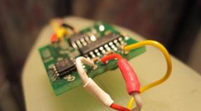
And this is what the board looks like, where everything is already soldered:

“Therma” has several varieties - here we can talk about the “Trio” model, it has been improved, some gadgets have been added to make the search more convenient and comfortable. The Trio already has 2-tone identification and, compared to older models, it is more convenient for them to search.
The Terminator 4 model is already considered obsolete, but those who started with it speak warmly of this model and continue to use it. It was “invented” already in 2007, while the “troika” is already 2009.
Three and four are most often single-tone devices (however, now two-tone models have also begun to be assembled), but the “Trio” is already 2-tone. So if you decide to buy a “thermal”, then it’s better to take a two-tone model. Still, when there is no display that helps in digging, and you have to navigate only by sound, then the more tones, the better. And here, single-tone homemade products, of course, lose out to factory devices, which have several tones by default.
There are also PRO models and a recent new product - 2012. We won’t talk about them here for now, because in price they are already comparable to professional-level devices.
Which is better, Terminator or Garrett Ace 250?
As you can see, this MD is practically in the same price category; the third “term” on thematic forums can be bought for 4-5 thousand rubles. Whereas 250 ICQ costs at least 2 times more.
However, at such a low price in terms of depth, “Thermal” makes Asya, it sees colored targets deeper. Of course, if everything is configured correctly and the operator fumbles.
On the other hand, ICQ’s convenience and information content are an order of magnitude higher, and if you are a complete newbie to coping, then I would advise you to take a factory device. And ICQ is still time-tested - a worthy entry-level device.
Does this MD have a pinpointer?
A pressing question, because now they have become more alert to installing DD coils on them, and without a pin they have to dig huge holes, and even the search technology, when you cross a target, does not help. The answer is that there is no pinpointer, and therefore we recommend purchasing an inexpensive manual pinpointer from this list.
How well does he see small targets?
The design of this MD is such that it sees “small things” just fine and easily copes with all entry-level devices - graters and ICQ. Again, let us remind you that it will be difficult to master this device from the very beginning.
What is this metal detector for - for coins or for war?
Here the answer suggests itself - most often this model is discussed on forums dedicated to war cops (in particular, Reibert), and therefore they use it for this purpose. They dig for shell casings, helmets, rifle bolts and other things of interest to war seekers. However, antique diggers who use these devices place it above the ICQ 250 and 34 Minelab graters, primarily in terms of detection depth.
Which MDs are “Terminator” most often compared to?
Most often they are compared with devices of the same level - in particular with the Cardinal Profi MD from the Sturmlab office. However, as diggers note, “Thermal” is more balanced, there are fewer glitches (Cardinal often starts if you wave the reel on dewy grass). Well, I also note that the food lasts longer.
In general, after talking with the comrade, I got the impression that the device is actually very worthy, well, it’s not for nothing that it has so many fans and admirers. Plus they are actively improving it, adding more and more new features.
And now I’ve already seen quite “sophisticated” metal detectors with a convenient panel and a pleasant design on sale. And in terms of characteristics, they say that they compete even with Minelab’s mid-range and top-end detectors - 705 grater and Exp. So this MD is worth paying attention to. Well, if you are comfortable with a soldering iron and fumble around with all sorts of circuits and transistors, then maybe you should try assembling it yourself? Fortunately, the Internet is full of schemes, and there are many thematic forums.
And finally, a video of a cop with Therm-4 - the quality is so-so, but what discoveries and most importantly - a new, lyrical song about diggers. I advise you to watch it even purely because of it. Well, you can clearly see that with this MD it is quite possible to dig for ancient coins.
One gets the feeling that there are simply no other signals, only coin ones) And there are no false ones either, which indicates good settling from the ground and the general setup of the device.
But here’s a test video about the “Trio” model - it’s more fun and clear:
A metal detector is a specific tool. Not every user may need this interesting device, but there are still plenty of people who want to purchase a metal detector or, as some call it, a metal detector. Of course, you can find and purchase a device for yourself, but why, if you have the opportunity to make it yourself, according to the diagram below for the metal detector - Terminator 3.
On the Internet you can find a large number of diagrams and instructions for making a metal detector with your own hands, but below one of the most popular variations will be presented homemade devices of such a type.
This version of the metal detector is considered by many to be one of the most popular. The inventors of such a reliable device are developers Yatogan and Radio Destroyer- both users of the md4u.ru forum. On this forum, by the way, you can find a lot more interesting things for those who want to assemble their own metal detector.

You just need to carefully prepare for the assembly process, which can be done by visiting the well-known forum md4u.ru.
Detection depth:
- Five Russian rubles - 22–24 cm;
- Catherine's nickel - 27–30 cm;
- Helmet - approximately 80 cm;
- Beer can - up to a whole meter.
Depth calculated for black soil with a sensor having 240 mm wire. By the way, we can say a few words about the discrimination of this metal detector. The fact is that while many similar devices are able to determine the location of a metal element at a certain depth, but cannot find out what kind of metal it is, Terminator-3 copes with this task. It can detect most metal objects at the maximum detection depth.
Assembling the Terminator-3 metal detector
 To assemble and set up this device you will need to use the following devices:
- multimeter;
- oscilloscope;
- LC meter;
- generator;
- frequency meter
Of course, if you purchase the entire set of presented devices yourself, you will have to spend money. But you can try to create virtual measuring complex yourself on the basis of the usual personal computer. By the way, you can find a fairly large number of programs for this purpose on the Internet.
Metal detector diagram:
 The Terminator-3 metal detector is one of the most popular devices of this type. In essence, it is a typical coin detector, which, having undergone some modifications, gained the ability to detect gold, while ignoring other non-ferrous metals.
In addition, even though Terminator-3 is a coin operator, it is also capable of searching for scrap metal, for which you simply have to introduce a special “all metals” mode into the circuit, since initially a circuit is taken that does not have this mode.
The circuit is implemented using non-standard logic as an op-amp. Of course, there is a certain disadvantage, which is that unknown CU of the microcircuits themselves, and the noise level is higher. You can apply domestic logic, but you will have to put up with a greater spread of parameters. It is possible, however, to replace it with a domestic sound generator microcircuit, without damage and without additional problems.
By the way, Terminator-3 in terms of such indicators as depth and accuracy of target identification is comparable to models of branded brands that are in the middle price range. When compared with cheaper branded analogues, Terminator-3 outperforms them in all respects. But for this to happen, you should assemble the metal detector as it should, and not as it turns out.
Description of setting up the Terminator-3 metal detector
 To begin with, you should pay attention to the nodes indicated in the diagram, since it is by them that you will have to navigate later. This will come in handy during the setup process. When connecting a transmitting coil (TX) to a self-oscillator) it begins to produce current fluctuations. These oscillations come out in the form of a meander from the MC1 microcircuit.
After this, you should move to the receiving coil (RX), which also contains a current induced by the TX and creating a field. According to this field, the coil should be balanced with the TX. In other words, it is necessary to subtract the RX field from the TX field. To do this, you will need a compensation coil (CX). For different sensors it appears differently: in the “RING” CX sensor it is real, in the form of a coil, and in the DD CX sensor it is virtual. It should be connected so that the current in it runs in the opposite direction to the receiving coil. By gradually unwinding from the compensation coil, balancing TX and RX in current is achieved.
The balancing is controlled by an oscilloscope, which allows you to achieve a minimum amplitude for all positions of the handle in turn. Upon reaching a certain point at which the amplitude begins to increase again, it begins act tuning loop, which is made from one of the ends of the compensation coil. Before this, be sure to adjust TX and RX in frequency, while RX is made 100 Hz lower than TX. The coils are tuned to the desired frequency by connecting each of them in turn to the oscilloscope and the instrument's generator.
 There is no need to adjust the CX frequency. A situation arises in which the balance is disrupted if a metal object appears under the sensor, As a result, current flows into RX, which from there falls into preamplifier, where it is then amplified and fed to a synchronization detector (SD), which, in turn, detects the phases of the incoming signal and outputs everything to the amplification channels. Everything is amplified in them and then goes to the MC8 comporator, whose task is to compare the signal levels in the channels, after which the comporator gives permission to operate the sound generator.
In principle, almost all balancers work this way, albeit with minor differences. The differences largely relate to the nuances of detuning the metal detector from the ground. Terminator 3 has phase detuning.
Checking the device board after final soldering:
In order to check the metal detector board after soldering all the circuit elements, you should carry out a series of procedures that will allow you to determine whether the circuit was soldered correctly.
To do this you need to do the following:

 A few words should be said about the low battery indication. It looks like this: the metal detector begins to send frequent signals at regular intervals. In this case, the diode should burn constantly, and the sensitivity drops sharply.
All settings for the frequency of the metal detector should be made with the same cable with which the device will subsequently be used. After the user has done everything necessary settings frequency, under no circumstances should he change the cable length.
Above is a picture that describes the sensitivity of the device. Some information is provided about several materials that can be detected by this metal detector.
Conclusion
In principle, assembling such a metal detector does not seem to be at all difficult. Yes, it may require effort, time and money, but there are a number of advantages that the user who finally assembles this metal detector receives as a bonus.
 Terminator-3 is a very strong device when compared to branded metal detector models, and given the fact that it can be made by hand, this makes it even nicer and preferable.
Of course, it will be much more difficult for the user to assemble such a device if he does not have the proper experience. But there are always manuals and instructions for beginner radio amateurs, who can find there a lot of interesting information for subsequent work with electronics.
If If you want to make a metal detector with your own hands, then in this article you will find detailed instructions. In particular, technical characteristics, circuits, settings, advantages and disadvantages of MD terminator 3.
DIY metal detector Terminator 3. Assembly instructions
MD terminator 3 is designed to detect objects containing metal in low-conductivity or dielectric array. With the help of MD terminator pro you can find metal in the soil, as well as at the bottom of various types of reservoirs.
Technical characteristics of MD Terminator-3
Main technical characteristics
- Metal detector type: selective
- Discrimination: yes
- Sensitivity adjustment: yes
- Soil balance adjustment: manual
- Operating modes: 2 pcs (“All metals”, “Discrimination”)
- Power: 6 AA batteries;
- Coil: 26cm DD waterproof
Test table Terminator M with DD-26cm sensor. (feel max, discrete on):
- Coin 5 kopecks Ø 25 mm ~ 40 cm.
- Fibula Ø35mm, length ~ 31 cm.
- Roman, denarius ~ 32 cm.
- Gold ring “engagement” Ø 19 ~ 37 cm.
- Silver chain Ø 26 grams. 925 samples ~ 30 cm
- Tin can ~ 67 cm.
- Leather wallet 30 USSR coins - 55 cm.
- Helmet ~ 92 cm.
- Sewer hatch ~ 145 cm.
- Maximum detection range (metal accumulation, tank) ~ 2 meters
Equipment:
- Metal detector block - 1 pc.
- Collapsible workshop rod - 1 pc.
- Batt compartment with power - 1 pc.
- Search coil - 1 pc.
- Coil fastening screw - 1 pc.
To the main technical specifications This type of device includes the following:
1) Detection depth;
2) Discrimination;
3) Ground balance.
Discrimination
This feature allows the metal detector to distinguish metals that it detects in the ground or
At the bottom of various types of reservoirs.
In this mode, the device can be configured for a specific type of metal, cutting off all others. You can also set the detection of all metals.

Detection depth
Most important parameter, which determines the effectiveness of using a metal detector.
A device with a 240 mm coil can recognize the following objects at a maximum distance:
· modern coins - 240 millimeters;
· five-kopeck coins from the time of Catherine the Great - 300 millimeters;
· military helmets - 800 millimeters.
Ground balance
Various kinds of objects falling into the magnetic field emitted by the device greatly distort it.
The soil can also introduce distortions. The level of
Imbalance.
The “soil balance” option is needed to filter out false impulses. The soil can be rebuilt automatically.
Making MDT 3 with your own hands
To create a Terminator 3 metal detector on your own, you need to follow the diagram.

MDT scheme 3
The figure below shows a plan for connecting radio components into one electrical circuit.
Link to full size diagram
Making a circuit board
To make the circuit board of the Terminator 3 metal detector on your own, you need to complete
The following sequence of actions:
- Search the Internet for photos circuit board metal detector terminator m.
- Printing the image on a printer in full size.
- Gluing paper onto a piece of PCB.
- Cutting the PCB with a hacksaw around the perimeter.
- Marking places for fastening parts with an awl.
- Drilling punctures.
- Cutting out current-carrying areas.
- Removing paper from conductive branches.
- Painting with bare paint.
- Removing remaining paper.
- Etching of metallized surface.
- Final cleaning of the board. 
Assembling the circuit and selecting parts
Before you begin assembling the metal detector, the terminator m should be selected for the circuit board
all components according to the parts list of the control unit for this type of device.
The assembly procedure for the Terminator Trio metal detector begins with jumpers. Then resistors are soldered
and panels for microcircuits. Next, the wires for the radio components are soldered. At the end of the process, make sure that the soldering is completedquality, and the radio components are installed correctly.
Insert the device control unit into the finished circuit.Place plastic handles on the switches, as well as on the resistor axes.Connect the terminals of the block to the sensor.
Components of the MDT 3 sensor
The metal detector sensor is round. Along its perimeter there are contours of enameled wire
ø 0.4 millimeters, which are
receiving and, accordingly, transmitting coils. The niche for the wires is made of dielectric material.
When assembling Terminator 3 with your own hands, place all the elements on the rod.
Make sure the sensor disk is securely attached.
Rechargeable battery, as well as the control unit for this type of device, install so that
it was possible to change operating modes while continuously searching for metals.
You need to embed a handle into the bar so that it is convenient to grasp it with your hand. If you wish, you can make an elbow rest from a plastic tube.
Adjustment and preparation for work
When testing the device in field conditions, the sensor should be brought closer to the ground surface and away from
Not. When the signal appears, you can remove it by turning the soil regulator knob.
Unwanted metals can be cut off by turning the discrimination knob. Sensitivity can be adjusted to depth
recognition of the desired metal.
Setting Discrimination
Terminator 3 is an IB metal detector with discrimination and very good performance! The main thing is that it is not difficult to set up and does not contain microcontrollers. The reduced diagram shows the main blocks of the device.
1. Power supply. I advise you to check its functionality before installing the microcircuits. When assembling a device without installed microcircuits and without coils, turn on the metal detector to check. Do not forget about the current, if it is very small and the voltages correspond to 6 and 4 volts, then you can move on! 2. Sound generator. I advise you to install the ms3 microcircuit first and apply power - you will hear a tone that will delight you when the metal detector detects a target. The tone can be changed by selecting c13 and resistors p14-15 3. RF generator. The main block that creates an emitted magnetic field that will be received reflected from the target. 4. Receiving amplifier. The functionality and importance of this unit is clear from the name. 5. Synchronizer. The key is on a 4066 chip. 6. Amplification channels. If you are assembling the device for yourself, pay attention to the selection of parts for the symmetry of the channels. I won’t pay attention to the filter and discharge indicator - these are not the main blocks.

You will find a clearer image of the MD T3 circuit and drawings of a printed circuit board for conventional radio components and SMD on the forum. Having assembled the Terminator 3 metal detector, having carried out an initial check of the functionality of the power supply and sound generator, we install the microcircuits and turn them on, while measuring the current without sound and coils. It can fluctuate from 10 to 30 mA, and with sound up to 50 mA. The current should not exceed these indicators if all the ratings of the parts are met.

At this stage, you can check the metal detector by setting knobs p7 (Disk) to 0k, p8 (BG) to 100K and resistor p39 (Senses) to set the sound to the threshold of failure. Touch the PX or c5 with your finger and the sound should briefly subside or disappear.

Now we wind the coils. I prefer the DD sensor - it’s easier to set up and you don’t need a cx coil - simple and convenient! First I made this template:

It’s not a tricky thing, but it allows you to repeat coils en masse and achieve identical half rings. To make such a template you need a base and material for the frame itself. Afterwards, we cut out the template, make a cut of about 1 cm for easy removal of the coil, and a cut in the base - also about 1 or 2 centimeters. As a wire receiver (let's call it that), I use electric staples, which punch wire No. 6 along the baseboard, and glue them around the perimeter with hot-melt adhesive - they are strong enough! We wind the coils with 0.4 mm wire into two wires of 30-35 turns. Then we tighten it with zip ties. And we remove it, tightening it with threads and removing the ties. After we tighten it with thin tape, we make a screen from aluminum tape without a gap, but with an overlap. And in order to avoid a short-circuited turn, we wrap it with tape in the place of overlap so that the foil does not touch each other. We solder the wire to the aluminum tape; there is no need to wrap it with tin! You can also add a layer of tape to seal the sensor. Then we wrap it in fiberglass and into a mold for pouring. We make the mold in foam plastic. To set up the discrimination of the T3 metal detector, you first need to prepare targets - copper (not copper-plated textolite), ferrite, also a piece of cigarette foil, an aluminum stopper and, if possible, coins. Now setup. It all starts with setting the sensor to the frequency. We connect the first coil to the generator with capacitance c1 and look at the frequency (remember, if necessary, you can lower or increase it with additional capacitance). Then we take the second coil and connect it to a generator with capacitance c2 and adjust the frequency one hundred hertz lower than the frequency of the first and it will be RX. Afterwards, we connect the coils to the MD in their places and reduce them to 0, measuring the amplitude at c5. Resistors BG = 100k, DISCRIM = 0, the switch is in color only mode and we begin to adjust the VDI scale. We take a piece of ferrite and pass it over the sensor - if there is no signal, then add capacitance to the TX, if there is one to the PX, until the ferrite is cut out 30-40 kOhm BG. Make sure the sensors are connected correctly by passing the ferrite and copper over the sensor, one signal for copper, double tone for ferrite. Then everything written above will work.

Each of us, when setting up a metal detector, has encountered, or will continue to do so, the need to adjust the metal detector, or rather the coils for it, to the desired frequency. Anyone who has a frequency meter, an inductance meter and an oscilloscope can, in principle, do it without the attachment recommended below. If there are no special devices, we make a simple device that turns the PC into a meter. All you need to assemble it is a connector, 4 resistors per 10 kohm. Jack in sound card your computer. So, we are looking for a connector, preferably one that matches the one that will later be placed on the body of your MD (coils can be connected directly to our device). I took a two-pair audio-video jack from the TV (these are found on VCRs, game consoles (dandy) and audio recorders). I carefully desoldered it, took a small piece of getinax, drilled holes in it for Jackie, soldered. Next, we move on to the markings - we separated the contact pads from the total mass (what is inside the tulip) and soldered a 10 kohm resistor.

At the other end of the board, I cut out 4 separate spots and soldered the remaining resistor leads to them. Here we have it small fee. In the bins I found two unnecessary wires (left over from some amplifier), on one end there is a jack - on the other there are 2 tulips (stereo jack). I cut off the ends, tinned the tulips, soldered the screens to the mask, and the central cores onto their heels on the board. We sign where each channel is on the board near the connectors (we check the ground with a tester - this is the edge, the first channel is the tip, the second channel is the middle). We connect the finished device to the computer, one jack is on line in, the other is line out. The main task then becomes the use of software. I use the SPECLAB, Oscilloscope, audioTester V1.4e program (the programs are on the website in the section). We connect the coil to the board the way it would be connected to the MD, to the connector leading from the line out and install the program with the generator. For work I use two programs:
1. audioTester V1.4g (generator of any shape, two-beam oscilloscope, spectrum analyzer).

2. SpectraLab V4.32.13 (frequency meter, spectrum analyzer, phase meter).

These programs work up to 44 kHz, but they are more than enough to work with a metal detector. Now let's move on to the setup. This setting is suitable for any MD, including the Terminator we are assembling, but here it will be described in relation to the Volkstrum-Sm circuit. First, we measure the frequency (SpectraLab): on U4B/12.13 - it should be 8192 Hz (if it’s a little different, we write down the value). 1. We install resistor R23 vertically and “bite off” the conductor connecting it to U4/1. Now we fix the coils so that there is no metal about one meter away. We turn on the audioTester program (generator) and connect it to R23, and the multimeter to connector JP4. By changing the frequency of the generator (in the program), we find the resonance at max. voltage on the multimeter. By selecting the exact value of the capacitance installed on the coil (adding small capacitances), we achieve resonance at 8192 Hz (or at the recorded value). We insert the receiving coil into connector JP4 and repeat the settings on it. 2. We restore the R23 gap and connect the coils to their regular places. We connect audioTester (oscilloscope mode) to U1A/1 and move the TX coil to achieve minimum readings. We fix the TX coil and repeat step 1. After several passes, we fix the position of the TX coil. Fill it with epoxy resin and connect the middle pin to the TX cable. We measure the values of the selected capacitances on each coil and replace them, if possible, with single containers with a small TKE. Capacitances are obtained in the region of 0.06 μF. We glue the plastic corners to attach the rod and cut off the excess pieces on the base.