Pic programmer scoop. How to program PIC microcontrollers or Simple JDM programmer. Manually assembled programmers
It just so happened that I started getting acquainted with microcontrollers with AVR. For the time being, I avoided PIC microcontrollers. But, nevertheless, they also have unique designs that are interesting to repeat! But these microcontrollers also need to be flashed. I am writing this article mainly for myself. In order not to forget technology, how to flash a PIC microcontroller without problems and waste of time.
How to program PIC microcontrollers or Simple JDM programmer
For the first circuit - I tried long and hard to make a PIC programmer using circuits found on the Internet - nothing came of it. It's a shame, but I had to turn to a friend to flash the MK. But it’s not a good idea to constantly run around with friends! This same friend recommended a simple circuit that works from a COM port. But even when I assembled it, nothing worked. After all, it’s not enough to assemble the programmer - you also need to customize the program for it, which we will use to flash it. But that’s exactly what I couldn’t do. There are a whole bunch of instructions on the Internet, and few of them helped me...
Then, I managed to flash one microcontroller. But since I was doing the stitching under severe time pressure, I didn’t think to save at least a link to the instructions. And I didn’t find her afterwards. Therefore, I repeat - I am writing an article to have my own instructions.
So, a programmer for PIC microcontrollers. Simple, although not 5 wires, as for AVR microcontrollers, which I still use today. Here's the diagram: 
Here is the printed circuit board (). 
The COM connector is soldered with pins directly onto the contact pads (the main thing is not to get confused with the numbering). The second row of pins is connected to the board with small jumpers (I said it very unclearly, yeah). I’ll try to give you a photo... even though it’s scary (I don’t have a normal camera right now).  The worst thing is that PIC microcontrollers require 12 volts for firmware. And it’s better not 12, but a little more. Let's say 13. Or 13.5 (by the way, experts - correct me in the comments if I'm wrong. Please.). 12 volts can still be obtained somewhere. Where is 13? I simply got out of the situation - I took a freshly charged lithium-polymer battery, which had 12.6 volts. Well, or even a four-cell battery, with its 16 volts (I flashed one PIC like this - no problem).
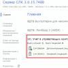
But I got distracted again. So - instructions for flashing PIC microcontrollers. We are looking for the WinPIC800 program (unfortunately, the simple and popular icprog did not work for me) and setting it up as shown in the screenshot.
 After that, open the firmware file, connect the microcontroller and flash it.

What first steps should a radio amateur take if he decides to assemble a circuit on a microcontroller? Naturally, a control program is needed - “firmware”, as well as a programmer.
And if there are no problems with the first point - the finished “firmware” is usually uploaded by the authors of the circuits, then with the programmer things are more complicated.
The price of ready-made USB programmers is quite high and the best solution will assemble it yourself. Here is a diagram of the proposed device (pictures are clickable).
Main part.

MK installation panel.

The original diagram was taken from the LabKit.ru website with the permission of the author, for which many thanks to him. This is a so-called clone of the proprietary PICkit2 programmer. Since the device version is a “lightweight” copy of the proprietary PICkit2, the author called his development PICkit-2 Lite, which emphasizes the ease of assembly of such a device for beginner radio amateurs.
What can a programmer do? Using the programmer, you can flash most readily available and popular PIC series MCUs (PIC16F84A, PIC16F628A, PIC12F629, PIC12F675, PIC16F877A, etc.), as well as 24LC series EEPROM memory chips. In addition, the programmer can operate in USB-UART converter mode and has some of the functions of a logic analyzer. A particularly important function that the programmer has is the calculation of the calibration constant of the built-in RC generator of some MCUs (for example, such as PIC12F629 and PIC12F675).

Necessary changes.
There are some changes in the circuit that are necessary so that using the PICkit-2 Lite programmer it is possible to write/erase/read data from EEPROM memory chips of the 24Cxx series.
From the changes that were made to the scheme. Added connection from pin 6 of DD1 (RA4) to pin 21 of the ZIF panel. The AUX pin is used exclusively for working with 24LC EEPROM memory chips (24C04, 24WC08 and analogues). It transmits data, which is why it is marked with the word “Data” on the programming panel diagram. When programming microcontrollers, the AUX pin is usually not used, although it is needed when programming MKs in LVP mode.
A 2 kOhm pull-up resistor has also been added, which is connected between the SDA and Vcc pins of the memory chips.
I have already made all these modifications on the printed circuit board, after assembling the PICkit-2 Lite according to the author’s original diagram.
24Cxx memory chips (24C08, etc.) are widely used in household radio equipment, and sometimes they have to be flashed, for example, when repairing CRT TVs. They use 24Cxx memory to store settings.
LCD TVs use a different type of memory (Flash memory). I have already talked about how to flash the memory of an LCD TV. If anyone is interested, take a look.
Due to the need to work with 24Cxx series microcircuits, I had to “finish” the programmer. Poison a new one printed circuit board I didn't, I just added the necessary elements on the printed circuit board. This is what happened.

The core of the device is a microcontroller PIC18F2550-I/SP.

This is the only chip in the device. The PIC18F2550 MK needs to be "flashed". This simple operation It causes stupor for many, as the so-called “chicken and egg” problem arises. I’ll tell you how I solved it a little later.
List of parts for assembling the programmer. IN mobile version drag the table to the left (swipe left-right) to see all its columns.
| Name | Designation | Rating/Parameters | Brand or item type |
| For the main part of the programmer | |||
| Microcontroller | DD1 | 8-bit microcontroller | PIC18F2550-I/SP |
| Bipolar transistors | VT1, VT2, VT3 | KT3102 | |
| VT4 | KT361 | ||
| Diode | VD1 | KD522, 1N4148 | |
| Schottky diode | VD2 | 1N5817 | |
| LEDs | HL1, HL2 | any 3 volt, red And green glow colors | |
| Resistors | R1, R2 | 300 Ohm | |
| R3 | 22 kOhm | ||
| R4 | 1 kOhm | ||
| R5, R6, R12 | 10 kOhm | ||
| R7, R8, R14 | 100 Ohm | ||
| R9, R10, R15, R16 | 4.7 kOhm | ||
| R11 | 2.7 kOhm | ||
| R13 | 100 kOhm | ||
| Capacitors | C2 | 0.1 μ | K10-17 (ceramic), imported analogues |
| C3 | 0.47 microns | ||
| Electrolytic capacitors | C1 | 100uF * 6.3V | K50-6, imported analogues |
| C4 | 47 uF * 16 V | ||
| Inductor (choke) | L1 | 680 µH | unified type EC24, CECL or homemade |
| Quartz resonator | ZQ1 | 20 MHz | |
| USB socket | XS1 | USB-BF type | |
| Jumper | XT1 | any type of "jumper" | |
| For microcontroller installation panel (MK) | |||
| ZIF panel | XS1 | any 40-pin ZIF panel | |
| Resistors | R1 | 2 kOhm | MLT, MON (power from 0.125 W and above), imported analogues |
| R2, R3, R4, R5, R6 | 10 kOhm | ||
Now a little about the details and their purpose.
Green LED HL1 lights up when power is applied to the programmer, and red The HL2 LED emits when data is transferred between the computer and the programmer.
To give the device versatility and reliability, an XS1 type “B” (square) USB socket is used. The computer uses a Type A USB socket. Therefore, it is impossible to mix up the sockets of the connecting cable. This solution also contributes to the reliability of the device. If the cable becomes unusable, it can be easily replaced with a new one without resorting to soldering or installation work.
As a 680 µH inductor L1, it is better to use a ready-made one (for example, types EC24 or CECL). But if you can’t find a finished product, you can make the throttle yourself. To do this, you need to wind 250 - 300 turns of PEL-0.1 wire onto a ferrite core from a CW68 type inductor. It is worth considering that due to the presence of PWM with feedback, there is no need to worry about the accuracy of the inductance rating.
The voltage for high voltage programming (Vpp) from +8.5 to 14 volts is created by the key regulator. It includes elements VT1, VD1, L1, C4, R4, R10, R11. PWM pulses are sent from pin 12 of the PIC18F2550 to the VT1 base. Feedback carried out by the divider R10, R11.
To protect circuit elements from reverse voltage from the programming lines when using a USB programmer in ICSP (In-Circuit Serial Programming) mode, a VD2 diode is used. VD2 is a Schottky diode. It should be selected with a voltage drop of P-N junction no more than 0.45 volts. Also, the VD2 diode protects elements from reverse voltage when the programmer is used in USB-UART conversion and logic analyzer mode.
When using the programmer exclusively for programming microcontrollers in the panel (without using ICSP), you can eliminate the VD2 diode completely (this is what I did) and install a jumper instead.
The compactness of the device is made by the universal ZIF panel (Zero Insertion Force - with zero installation effort).

Thanks to it, you can “hardwire” a microcontroller into almost any DIP package.
The diagram "Microcontroller (MK) installation panel" indicates how microcontrollers with different housings must be installed in the panel. When installing the MK, you should pay attention to the fact that the microcontroller in the panel is positioned so that the key on the chip is on the side of the ZIF panel locking lever.
This is how you need to install 18-pin microcontrollers (PIC16F84A, PIC16F628A, etc.).

And here are 8-pin microcontrollers (PIC12F675, PIC12F629, etc.).

If you need to flash a microcontroller in a surface-mount package (SOIC), you can use an adapter or simply solder 5 pins to the microcontroller that are usually required for programming (Vpp, Clock, Data, Vcc, GND).

You can find the finished drawing of the printed circuit board with all the changes at the link at the end of the article. By opening the file in the Sprint Layout 5.0 program, using the “Print” mode, you can not only print a layer with a pattern of printed conductors, but also view the positioning of elements on the printed circuit board. Pay attention to the isolated jumper that connects pin 6 of DD1 and pin 21 of the ZIF panel. You need to print the board drawing in mirror image.
You can make a printed circuit board using the LUT method, as well as a marker for printed circuit boards, using tsaponlak (this is what I did) or the “pencil” method.

Here is a picture of the positioning of elements on a printed circuit board (clickable).

When installing, the first step is to solder jumpers made of tinned copper wire, then install low-profile elements (resistors, capacitors, quartz, ISCP pin connector), then transistors and a programmed MK. The last step is to install the ZIF panel, USB socket and seal the wires in insulation (jumpers).
"Firmware" of the PIC18F2550 microcontroller.
Firmware file - PK2V023200.hex you need to write the PIC18F2550I-SP MK into the memory using any programmer that supports PIC microcontrollers (for example, Extra-PIC). I used the JDM Programmator JONIC PROG and the program WinPic800.

You can upload the firmware to the PIC18F2550 MCU using the same proprietary programmer PICkit2 or its new version PICkit3. Naturally, you can do this with a homemade PICkit-2 Lite, if one of your friends managed to assemble it before you :).
It is also worth knowing that the “firmware” of the PIC18F2550-I/SP microcontroller (file PK2V023200.hex) is written when installing the PICkit 2 Programmer program in a folder along with the files of the program itself. Approximate location of the file PK2V023200.hex - "C:\Program Files (x86)\Microchip\PICkit 2 v2\PK2V023200.hex" . For those who have 32-bit installed on their PC Windows version, the location path will be different: "C:\Program Files\Microchip\PICkit 2 v2\PK2V023200.hex" .
Well, if you couldn’t solve the “chicken and egg” problem using the proposed methods, then you can buy a ready-made PICkit3 programmer on the AliExpress website. It costs much cheaper there. About how to buy parts and electronic kits I wrote on AliExpress.
Updating the programmer firmware.
Progress does not stand still and from time to time Microchip releases updates for its software, including for the PICkit2, PICkit3 programmer. Naturally, we can update control program his homemade PICkit-2 Lite. To do this you will need the PICkit2 Programmer program. What it is and how to use it - a little later. In the meantime, a few words about what needs to be done to update the firmware.
To update the programmer software, you must close jumper XT1 on the programmer when it is disconnected from the computer. Then connect the programmer to the PC and launch PICkit2 Programmer. When XT1 is closed, the mode is activated bootloader to download the new firmware version. Then in PICkit2 Programmer, through the menu “Tools” - “Download PICkit 2 Operation System”, open the previously prepared hex file of the updated firmware. Next, the programmer software update process will occur.
After the update, you need to disconnect the programmer from the PC and remove the XT1 jumper. In normal mode the jumper is open. You can find out the programmer software version through the "Help" - "About" menu in the PICkit2 Programmer program.
It's all about technical issues. And now about the software.
Working with the programmer. PICkit2 Programmer.
To work with the USB programmer, we will need to install the PICkit2 Programmer program on the computer. This special program It has a simple interface, is easy to install and does not require special configuration. It is worth noting that you can work with the programmer using the MPLAB IDE development environment, but in order to flash/erase/read the MK, a simple program - PICkit2 Programmer is enough. I recommend.
After installing the PICkit2 Programmer program, connect the assembled USB programmer to the computer. At the same time it will light up green LED ("power"), and operating system recognizes the device as "PICkit2 Microcontroller Programmer" and install the drivers.
Launch the PICkit2 Programmer program. An inscription should appear in the program window.

If the programmer is not connected, a scary message will appear in the program window and brief instructions"What to do?" in English.

If the programmer is connected to a computer with an MK installed, the program will detect it when launched and will notify us about it in the PICkit2 Programmer window.

Congratulations! The first step has been taken. And I talked about how to use the PICkit2 Programmer program in a separate article. Next step .
Required files:
PICkit2 User Manual (Russian) take or.
PIC microcontrollers have earned fame due to their unpretentiousness and quality of operation, as well as versatility in use. But what can a microcontroller do without the ability to write new programs onto it? Without a programmer, this is nothing more than a piece of amazingly shaped hardware. The PIC programmer itself can be of two types: either home-made or factory-made.
The difference between factory and homemade programmers
First of all, they are distinguished by the reliability and functionality that they provide to microcontroller owners. So, if you make a homemade one, then, as a rule, it is designed for only one model of PIC microcontroller, while the programmer from Microchip provides the ability to work with various types, modifications and models of microcontrollers.
Factory programmer from Microchip

The most famous and popular is the simple PIC programmer, which is used by many people and is known to many as PICkit 2. Its popularity is due to its obvious and hidden advantages. The obvious advantages that this has USB programmer for PIC, it is possible to list for a long time, among them: relatively low cost, ease of operation and versatility relative to the entire family of microcontrollers, ranging from 6-pin to 20-pin.
Using a programmer from Microchip
You can find many tutorials on its use that will help you understand all sorts of aspects of its use. If we consider not only a PIC programmer purchased second-hand, but purchased from an official representative, then we can also notice the quality of support provided with it. So, in addition there are training materials on use, licensed development environments, as well as a demo board, which is designed to work with low-pin microcontrollers. In addition to all this, there are utilities that will make working with the mechanism more enjoyable and will help monitor the process of programming and debugging the microcontroller. A utility is also supplied to stimulate the operation of the MK.

Other programmers
In addition to the official programmer, there are others that allow you to program microcontrollers. When purchasing them, you don’t have to count on additional software, but for those who don’t need more, this is enough. A rather obvious disadvantage is that for some programmers it is difficult to find the necessary software to be able to work efficiently.
Manually assembled programmers
And now, perhaps, the most interesting thing is the PIC controller programmers, which are assembled manually. This option is used by those who do not have money or simply do not want to spend it. If you purchase from an official representative, you can count on the fact that if the device turns out to be of poor quality, you can return it and get a new one in exchange. And when buying “from hand” or using bulletin boards in case of poor-quality soldering or mechanical damage You can’t count on reimbursement of expenses and receiving a quality programmer. Now let's move on to the hand-assembled electronics.
The PIC programmer can be designed for specific models or be universal (for all or almost all models). They are assembled on microcircuits that can convert signals from the RS-232 port into a signal that will allow programming the MK. You need to remember that when you assemble a design given by someone, the PIC programmer, the circuit and the result must match one to one. Even small deviations are undesirable. This remark applies to beginners in electronics; people with experience and practice can improve almost any circuit if there is room for improvement.

It’s worth saying a special word about software package, which they provide a DIY USB programmer for PIC. The fact is that it is not enough to assemble the programmer itself according to one of the many schemes presented on the world wide web. You also need software that will allow the computer to flash the microcontroller with its help. Icprog, WinPic800 and many other programs are often used as such. If the author of the programmer circuit himself did not indicate the software with which his creation can do its job, then you will have to find out yourself by brute force. The same applies to those who assemble their own circuits. You can write a program for MK yourself, but this is real aerobatics.
Universal programmers that are suitable not only for RIS
If a person is interested in programming microcontrollers, then it is unlikely that he will constantly use only one type. For those who do not want to buy separate programmers for various types microcontrollers, from various manufacturers, They were designed universal devices, who will be able to program MKs of several companies. Since there are quite a few companies producing them, it’s worth choosing a couple and talking about the programmers for them. The choice fell on the giants of the microcontroller market: PIC and AVR.

The universal PIC and AVR programmer is equipment whose peculiarity lies in its versatility and the ability to change the operation thanks to the program without making changes to the hardware component. Thanks to this property, such devices easily work with microcontrollers that were released for sale after the release of the programmer. Considering that the architecture will not change significantly in the near future, they will be suitable for use for a long time. Additional pleasant properties of factory programmers include:
- Significant hardware restrictions on the number of programmable microcircuits, which will allow programming not one, but several pieces of electronics at once.
- Possibility of programming microcontrollers and circuits based on various technologies (NVRAM, NAND Flash and others).
- Relatively short programming time. Depending on the programmer model and the complexity of the programmed code, it may take from 20 to 400 seconds.
Features of practical use

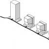
Separately, it is worth touching on the topic of practical use. As a rule, programmers are connected to USB ports, but there are also variations that work using the same wires as the hard drive. And to use them you will have to remove the computer cover, sort out the wires, and the connection process itself is not very convenient. But the second type is more versatile and powerful, thanks to it the firmware speed is faster than when connected via USB. Using the second option does not always seem to be such a convenient and comfortable solution as with USB, because before using it you need to do a number of operations: take out the case, open it, find the necessary wire. You don’t have to worry about possible problems from overheating or power surges when working with factory models, since they usually have special protection.
Working with microcontrollers
What is necessary for all programmers with microcontrollers to work? The fact is that, although the programmers themselves are independent circuits, they transmit computer signals in a certain sequence. And the problem of how to explain to the computer what exactly needs to be sent is solved by the programmer software.
There are quite a lot of different programs available in the public domain that are aimed at working with programmers, both home-made and factory-made. But if it is manufactured by a little-known company, was made according to the design of another electronics enthusiast, or by the person reading these lines himself, then software you may not find it. In this case, you can use a search of all available programming utilities, and if none of them work (if you are sure that the programmer works well), then you need to either take/make another PIC programmer, or write own program, which is quite aerobatics.

Possible problems
Alas, even the most ideal technology is not without possible problems, which no, no, and will arise. For improved understanding, it is necessary to make a list. Some of these problems can be corrected manually with a detailed inspection of the programmer, others can only be checked if you have the necessary testing equipment. In this case, if the PIC microcontroller programmer is factory-made, it is unlikely to be repaired. Although you can try to find possible reasons failures:
- Poor quality soldering of programmer elements.
- Lack of drivers to work with the device.
- Damage inside the programmer or wires inside the computer/USB.
Experiments with microcontrollers
So, everything is there. How to start working with equipment, how to start flashing a microcontroller with a programmer?
- To plug external power supply, connect all equipment.
- Initially, an environment is needed with the help of which everything will be done.
- Create the required project, select the microcontroller configuration.
- Prepare a file containing all the necessary code.
- Connect to the programmer.
- When everything is ready, you can flash the microcontroller.
The above was written only general scheme, which allows you to understand how the process occurs. For individual development environments it may differ slightly, and more detailed information about them can be found in the instructions.
I would like to write a separate appeal to those who are just starting to use programmers. Remember that, no matter how basic some steps may seem, you must always adhere to them so that the equipment can work normally and adequately and perform the tasks you set. Good luck in electronics!
1. PROGRAMMER FOR PIC CONTROLLERS
I hope that my article will help some radio amateurs cross the threshold from digital technology to microcontrollers. There are many programmers on the Internet and in amateur radio magazines: from the simplest to the most sophisticated. Mine is not very complicated, but reliable.
The first version of the programmer is designed for programming 18 and 28 pin PIC controllers. The programmer is based on a diagram from Radio No. 10 magazine for 2007. But selecting the C7 capacitor and experimenting with different variants of ICprog, PonyProg, WinPic and read-write speeds did not give the desired result: successful programming was achieved every once in a while. And this continued until the +5V power supply of the programmable microcircuit was made separately, and not after a 12-volt stabilizer. The result is the following diagram.

Fearing failures, I drew the signet so that the board was inserted directly into the Com port, which is not very easy due to all kinds of “laces” and the short distance to the case. The signet turned out to be of irregular shape, but it is inserted into the COM port normally and programs without errors.

Over time, I made an extension cord about 1 meter long. Now the programmer lies next to the monitor and is connected to the COM port. It works fine: microcontrollers PIC16F84A, PIC16F628A, PIC16F873A have been programmed many times.
Please note: the Max chip and LEDs are installed on the side of the printed conductors. The sockets are ZIF-28, one of them is used for 18-pin PIC. The panels bear the marks of the first legs and the numbers “18” and “28”. A 220 15 volt, 4 watt transformer is installed in the adapter plug housing. You need to plug it into the outlet after installing the microcontroller in the socket. Transistors npn low-power high-frequency (300 MHz) in a to-92 package.
I didn’t install the XP connector for a while, and then it turned out that it wasn’t really needed. I had to somehow program the soldered MK, so I inserted the wires directly into the ZIF and fixed it. Reprogramming was successful.
I work with ICprog and WinPic-800 programs.
The IC-prog 1.05D program has the following programmer settings:
- Programmer – JDM Programmer
- Port –Com1
- Direct access to ports.
- Inversion: input, output and clocking (check the boxes).
In WinPic-800 –v.3.64f everything is identical, you just need to install the “bird” in using MCLR.
You can download these programs freely and freely on the Internet. But to make life easier, I will try to do everything necessary. I just remembered how many “unnecessary things” I myself downloaded from the Internet, and how much time I spent sorting it all out.
- Programmer circuit board
- WinPic-800 program ( )
- Program IC-Prog()
- Article on IC-Prog.
2. PROGRAMMER-2 FOR PIC CONTROLLERS
Over time, the need arose to program 14 and 40 “pin” peaks. I decided to make a programmer for the entire average family of PICs. The scheme is the same, only two panels have been added. All this is housed in a housing from a former multimeter.


A correction was made to the printed circuit board on February 13, 2014: from the 5th pin of the RS232 connector, the track goes to the power supply minus (and on the previous one, to the 6th pin of the MAX chip). New signet in "programer2-2".
You can save one Kren. Those. connect the entire circuit from one 5-volt stabilizer. Do not install VR3 and C9, but install a jumper (indicated by a dotted line in the diagram). But I haven’t soldered Krenka yet. Programmed PIC16F676, 628A, 84A and 873A many times. But I haven't tried 877 yet.
Some capacitors are installed on the side of the printed conductors. The rollers are located in a horizontal position. In order not to lay conductors, I installed C7 - 2 pcs and R12 - 3 pcs.
Very important: the housing of the RS232 connector must be connected to the power supply minus.
The power supply (15 V) and programs are the same as in the first option.
List of radioelements
| Designation | Type | Denomination | Quantity | Note | Shop | My notepad | |
|---|---|---|---|---|---|---|---|
| Scheme 1 | |||||||
| DD1 | RS-232 interface IC | MAX232E | 1 | MAX232CPE | To notepad | ||
| VT1-VT4 | Bipolar transistor | 2N3904 | 4 | TO-92 | To notepad | ||
| VDS1 | Diode bridge | DB157 | 1 | To notepad | |||
| VD1 | Rectifier diode | 1N4148 | 1 | To notepad | |||
| VR1, VR3 | Linear regulator | L7805AB | 1 | To notepad | |||
| VR2 | Linear regulator | KA78R12C | 1 | To notepad | |||
| C1 | 470 µF 35V | 1 | To notepad | ||||
| C2, C3, C5, C6 | Electrolytic capacitor | 10 µF 50V | 4 | To notepad | |||
| C4, C8 | Electrolytic capacitor | 470 µF 16V | 2 | To notepad | |||
| C7 | Electrolytic capacitor | 1 µF 25V | 1 | To notepad | |||
| C11 | Capacitor | 0.1 mF | 1 | To notepad | |||
| R1, R7 | Resistor | 10 kOhm | 2 | To notepad | |||
| R2 | Resistor | 470 Ohm | 1 | To notepad | |||
| R3, R5, R11 | Resistor | 4.7 kOhm | 3 | To notepad | |||
| R4, R10 | Resistor | 2 kOhm | 2 | To notepad | |||
| R6, R8, R9 | Resistor | 1 kOhm | 3 | To notepad | |||
| R12 | Resistor | 240 Ohm | 1 | To notepad | |||
| HL1 | Light-emitting diode | 1 | Red | To notepad | |||
| HL2 | Light-emitting diode | 1 | Green | To notepad | |||
| Scheme 2 | |||||||
| DD1 | RS-232 interface IC | MAX232E | 1 | MAX232CPE | To notepad | ||
| VT1-VT4 | Bipolar transistor | 2N3904 | 4 | TO-92 | To notepad | ||
| VDS1 | Diode bridge | DB157 | 1 | To notepad | |||
| VD1 | Rectifier diode | 1N4148 | 1 | To notepad | |||
| VR1, VR3 | Linear regulator | L7805AB | 2 | To notepad | |||
| VR2 | Linear regulator | KA78R12C | 1 | To notepad | |||
| C1, C2, C4, C5 | Capacitor | 10uF 50V | 4 | To notepad | |||
| C3 | Electrolytic capacitor | 470uF 35V | 1 | To notepad | |||
| C6, C9 | Electrolytic capacitor | 470uF 16V | 2 | To notepad | |||
| C7.1-C7.3 | Capacitor | 0.1 µF | 3 | ||||
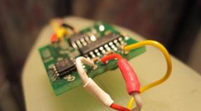
The proposed programmer is based on a publication from the magazine “Radio” No. 2, 2004, “Programming modern PIC16, PIC12 on PonyProg.” This is my first programmer that I used to flash PIC chips at home. The programmer is a simplified version of the JDM programmer, the original circuit has an RS-232 to TTL converter in the form of a MAX232 microcircuit, it is more universal, but you can’t assemble it “on your knees”. This scheme has no active components at all, does not contain scarce parts and is very simple, can be assembled without the use of a printed circuit board.
Rice. 1: Schematic diagram programmer
Description of the circuit operation
The programmer circuit is shown in Fig. 1. Resistors in the CLK (clocking), DATA (information), Upp (programming voltage) circuits serve to limit the flow of current. PIC controllers are protected from breakdown by built-in zener diodes, so there is some compatibility between TTL and RS-232 logic. The presented circuit contains diodes VD1, VD2, which “take” the positive voltage from the COM port relative to pin 5 and transfer it to power the controller, thanks to which in some cases it is possible to get rid of an additional power source.
Setting up
In practice, it does not always happen that this programmer will work without adjustment, on the first try, because... The operation of this circuit is highly dependent on the parameters of the COM port. However, for me, on two mother's Gigabyte boards 8IPE1000 and WinFast under XP, everything worked right away. If you are too lazy to deal with a broken, more complex programmer circuit, then you should try to assemble this one. Here are some things that may affect:
The newer the mat. board, the developers pay less attention to these ports, because these ports have long become obsolete. You can get rid of this by purchasing a USB-COM adapter, although again the purchased device may not be suitable. The required parameters are: variable voltage should change at least -10V to +10V (log. 0 and 1) relative to the 5th pin of the connector. The supplied current must be at least such that when a 2.7 kOhm resistor is connected between the 5th contact and the contact under test, the voltage does not drop below 10V (I have not seen such boards myself). Also, the port must correctly determine the voltages coming from the controller; at a voltage level close to 0V, but not more than 2V, zero is determined, and accordingly, at a voltage level above 2V, one is determined.
Problems may also arise due to software.
This is especially true for LINUX OS, because... Due to the presence of emulators such as wine, VirtualBox, ports may not work correctly, and a lot of capabilities are required from them. I will touch on these problems in more detail in another article.
Knowing these features, let's start setting it up.
For this, it is very desirable to have the ICProg 1.05D program.
In the program menu, you must first select the appropriate setting in the settings. port (COM1. COM2), select JDM programmer. Then open the “Hardware Check” window, in the “Settings” menu. In this menu, you need to check the boxes one by one and use a voltmeter to measure the voltage at the contacts of the connected connector. If the voltage parameters do not correspond to the norm, then, unfortunately, this may be the cause of inoperability, then you will have to assemble a circuit with an RS-232 TTL converter. Having checked all the boxes, you need to make sure that a supply voltage of about 5V is generated at the zener diode. If the voltages are normal and there are no installation errors, then everything should work. We put the controller in the socket, open the firmware, program it. There is no need to enable checkboxes like “Invert data out” (all are unchecked). Also, do not forget that some batches of controllers may not have exactly standard parameters, and it is not possible to flash them, in such cases with this programmer you can only try to reduce the supply voltage from 5V to 3-4V by connecting the corresponding zener diode, look at the controller for erroneous activation of the LVP (low-voltage programming) mode, how to prevent it, you can read on the Internet for a specific type of controller. It is probably possible to increase the programming voltage of the problematic controller only by complicating the circuit by introducing an amplification stage with a common emitter, powered from an additional power source.
Now let's talk more about the problem with the device's power supply. The programmer was tested with ICProg programs and console picprog under Linux, it should work with any that supports JDM if you connect an additional power source (it is connected through a 1 kOhm resistor to the zener diode, diodes with resistors in this case can be completely excluded). The fact is that the programmer control algorithms for individual software are different, the ICProg program is the most unpretentious. It was noticed that in Windows OS this program raised the required supply voltage on unused pin 2, the same program under the emulator in Linux to another mat. The board was no longer able to do this, but a way out was found by taking power from the programming voltage. In general, I think you can use this programmer with ICProg without additional power. With other software this is unlikely to be guaranteed, for example, the “native” picprog from the Ubuntu repositories without power simply does not detect the programmer, displaying the message “JDM hardware not found" It probably either receives some data without applying the programming voltage, or does it too quickly, so that the filter capacitor does not yet have time to charge.