Creating a cluster of 2 computers. Desktop cluster
First of all, decide what components and resources you will need. You will need one main node, at least a dozen identical compute nodes, an Ethernet switch, a power distribution unit and a rack. Determine the wiring and cooling capacity, as well as the amount of space you will need. Also decide what IP addresses you want to use for the nodes, what software you will install, and what technologies you will need to create parallel computing power (more on this below).
- Although hardware is expensive, all the programs presented in this article are distributed free of charge, and most of them are open source.
- If you want to find out how fast your supercomputer could theoretically be, use this tool:
Mount the nodes. You will need to assemble network nodes or purchase pre-assembled servers.
- Choose server frames that maximize space, energy efficiency, and cooling performance.
- Or you can “recycle” a dozen or so used servers, a few outdated ones - and even if their weight exceeds the total weight of the components, but you will save a decent amount. All processors network adapters and motherboards must be the same for the computers to work well together. Of course, don't forget about RAM and hard disks for each node, as well as at least one optical drive for the main node.
Install the servers in the rack. Start from the bottom so that the rack is not overloaded at the top. You'll need a friend's help - the assembled servers can be very heavy, and placing them in the cages that hold them in the rack is quite difficult.
Install an Ethernet switch next to the rack. It's worth configuring the switch right away: set the size of jumbo frames to 9000 bytes, set the static IP address that you chose in step 1 and turn off unnecessary protocols such as SMTP.
Install a power distribution unit (PDU, or Power Distribution Unit). Depending on the maximum load the nodes on your network can handle, you may need 220 volts for your high-performance computer.
When everything is installed, proceed to configuration. Linux is, in fact, the go-to system for high-performance (HPC) clusters - not only is it ideal as a scientific computing environment, but you also don't have to pay to install the system on hundreds or even thousands of nodes. Imagine how much it would cost Windows installation to all nodes!
- Start with installation latest version BIOS for the motherboard and software from the manufacturer, which must be the same for all servers.
- Set your preferred Linux distribution for all nodes, and for the main node - a distribution kit with a graphical interface. Popular systems: CentOS, OpenSuse, Scientific Linux, RedHat and SLES.
- The author highly recommends using Rocks Cluster Distribution. In addition to installing all the software and tools needed for a cluster, Rocks provides an excellent method for quickly "migrating" multiple copies of a system to similar servers using PXE boot and Red Hat's "Kick Start" procedure.
Install the message passing interface, resource manager and other required libraries. If you did not install Rocks in the previous step, you will have to manually install the necessary software to configure the parallel computing logic.
- To get started, you'll need a portable bash system, such as Torque Resource Manager, which allows you to split and distribute tasks across multiple machines.
- Add Maui Cluster Scheduler to Torque to complete the installation.
- Next you need to install a message passing interface, which is necessary to ensure that individual processes in each individual node use the common data. OpenMP is the simplest option.
- Don't forget about multi-threaded math libraries and compilers that will “assemble” your programs for distributed computing. Did I mention you should just play Rocks?
Connect computers into a network. The main node sends tasks for calculation to slave nodes, which in turn must return the result back, and also send messages to each other. And the faster all this happens, the better.
- Use private Ethernet network to connect all nodes into a cluster.
- The master node can also act as an NFS, PXE, DHCP, TFTP and NTP server when connected to Ethernet.
- You must separate this network from the public ones to ensure that packets do not overlap with others on the LAN.
Test the cluster. The last thing you should do before giving users access to computer power is to test the performance. HPL (High Performance Lynpack) benchmark is a popular option for measuring computing speed in a cluster. You need to compile the software from source to the highest degree of optimization that your compiler allows for the architecture you choose.
- You should of course compile with all possible settings optimizations that are available for the platform you choose. For example, when using an AMD CPU, compile to Open64 and optimization level -0.
- Compare your results with TOP500.org to pit your cluster against the 500 fastest supercomputers in the world!
I built my first “cluster” of single-board computers almost immediately after the Orange Pi PC microcomputer began to gain popularity. It could be called a “cluster” with great stretch, because from a formal point of view it was just the local network of four boards that “saw” each other and could access the Internet.
The device participated in the SETI@home project and even managed to count something. But, unfortunately, no one came to pick me up from this planet.
However, during all this time fiddling with wires, connectors and microSD cards, I learned a lot. So, for example, I found out that you shouldn’t trust the declared power of the power supply, that it would be nice to distribute the load in terms of consumption, and the cross-section of the wire matters.
And yes, we had to “collectively farm” the power management system, because the simultaneous start of five single-board devices may require a starting current of the order of 8-10A (5*2)! This is a lot, especially for power supplies made in the basements of the country, where we love to order all sorts of... interesting gadgets.
I'll probably start with her. The task came down to relatively simple actions - after a given period of time, sequentially turn on 4 channels through which 5 volts are supplied. The easiest way to implement your plan is Arduino (of which every self-respecting geek has an abundance) and this miracle board from Ali with 4 relays.
And you know, it even worked.


However, the “refrigerator-style” clicks at startup caused some discomfort. Firstly, when there was a click, interference ran through the power supply and it was necessary to install capacitors, and secondly, the entire structure was quite large.
So one day I simply replaced the relay block with transistor switches based on IRL520.

This solved the issue with interference, but since the mosfet controls the “zero”, I had to abandon the brass legs in the rack so as not to accidentally connect the ground of the boards.
And now, the solution is being replicated perfectly and two clusters are already working stably without any surprises. Just as planned.

But let's return to replication. Why buy power supplies for a significant amount of money when there are many affordable ATXs literally under your feet?
Moreover, they have all the voltages (5,12,3.3), the beginnings of self-diagnosis and the possibility of program control.
Well, I won’t go into too much detail here - an article about controlling ATX via Arduino.
Well, are all the pills eaten, and the stamps are also stuck on? It's time to put it all together.

There will be one head node that connects to the outside world via WiFi and sends the “Internet” to the cluster. It will be powered by ATX standby voltage.
In fact, TBNG is responsible for distributing the Internet.
So, if desired, cluster nodes can be hidden behind TOR.
Also, there will be a tricky board connected via i2c to this head node. It will be able to turn on/off each of the 10 worker nodes. Plus, it will be able to control three 12V fans to cool the entire system.
The operating scenario is as follows: when ATX is turned on at 220V, the head node starts. When the system is ready for operation, it sequentially turns on all 10 nodes and fans.
When the switching process is completed, the head node will go around each working node and ask how we feel, what is the temperature. If one of the racks gets hot, increase the airflow.
Well, with a shutdown command, each of the nodes will be carefully turned off and de-energized.
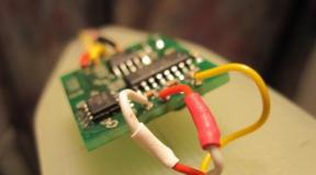
I drew the board diagram myself, so it looks creepy. However, a well-trained person took on the tracing and manufacturing, for which we thank him very much.
Here it is in the process of being assembled

Here is one of the first sketches of the location of the cluster components. Made on a checkered piece of paper and immortalized through Office Lens by the phone.

The entire structure is placed on a sheet of textolite purchased for the occasion.
This is roughly what the location of the nodes inside looks like. Two racks of five cards each.

Here you can see the Arduino control. It is connected to the head Orange Pi Pc via i2c via a level converter.
Well, here is the final (current version).

So, all you need is to write several utilities in Python that would conduct all this music - turn on, turn on, adjust the fan speed.
I won’t bore you with technical details - it looks something like this:
| 1
2 3 4 5 6 7 8 | #!/usr/bin/env sh echo "Starting ATX board..." /home/zno/i2creobus/i2catx_tool.py --start echo "Setting initial fan values..." /home/zno/i2creobus/i2creobus_tool.py --fan 0 --set 60 /home/zno/i2creobus/i2creobus_tool.py --fan 1 --set 60 /home/zno/i2creobus/i2creobus_tool.py --fan 2 --set 60 |
Since we already have as many as 10 nodes, we use Ansible, which will help, for example, to correctly turn off all nodes. Or run a temperature monitor on each.
| 1
2 3 4 5 6 7 8 | ---
- hosts: workers roles: - webmon_stop - webmon_remove - webmon_install - webmon_start |
I am often accused in a dismissive tone, saying that this is just a local single-plate network (as I already mentioned at the very beginning). In general, I don’t give a damn about other people’s opinions, but perhaps we’ll add some glamor and organize a docker swarm cluster.
The task is very simple and can be completed in less than 10 minutes. Then we launch an instance of Portainer on the head node, and voila!

Now you can really scale tasks. Thus, the Verium Reserve cryptocurrency miner is currently running in the cluster. And quite successfully. I hope the nearest native will recoup the consumed electricity;) Well, or reduce the number of nodes involved and mine something else like Turtle Coin.

If you want a payload, you can throw Hadoop into the cluster or arrange balancing of web servers. There are a lot of ready-made images on the Internet, and there is enough training material. Well, if the image (docker image) is missing, you can always build your own.
What did this teach me? In general, the technology “stack” is very broad. Judge for yourself - Docker, Ansible, Python, upgrading Arduino (God forgive me, it won’t be said by night), and the shell, of course. And also KiCad and working with a contractor :).
What can be done better? Much. On the software side, it would be nice to rewrite control utilities in Go. By the way - make it more steampunkish - KDPV at the beginning perfectly raises the bar. So there is something to work on.
Roles performed by:
- Head node - Orange Pi PC with usb wifi.
- Working nodes - Orange Pi PC2 x 10.
- Network - 100 Mbit TP-link@16ports.
- Brain - Arduino clone based on Atmega8 + level converter.
- The heart is an ATX power controller with a power supply.
- Software (soul) - Docker, Ansible, Python 3, a little shell and a little laziness.
- The time spent is priceless.
During the experiments, a couple of Orange Pi PC2 boards were damaged due to a mixed-up power supply (they burn very beautifully), another PC2 lost Ethernet (this is a separate story in which I do not understand the physics of the process).
That seems to be the whole story “from top to bottom.” If anyone finds it interesting, ask questions in the comments. And vote for questions there (upvote - each comment has a button for this). Most interesting questions will be covered in new notes.
Thank you for reading to the end.
(By the way, it is possible to assemble an inexpensive and efficient cluster from an xbox 360 or PS3, the processors there are about the same as Power, and you can buy more than one console for a million.)
Based on this, we note interesting price options for building a high-performance system. Of course, it must be multiprocessor. Intel uses Xeon processors for such tasks, while AMD uses Opteron processors.
If there is a lot of money

 Separately, we note the extremely expensive but productive line of processors based on the Intel Xeon LGA1567 socket.
 The top processor in this series is the E7-8870 with ten 2.4 GHz cores. Its price is $4616. For such CPUs, HP and Supermicro produce! eight-processor! server chassis. Eight 10-core Xeon E7-8870 2.4 GHz processors with HyperThreading support support 8*10*2=160 threads, which is in the manager Windows tasks displayed as one hundred and sixty processor load graphs, with a 10x16 matrix.
In order for eight processors to fit in the case, they are not placed immediately on motherboard, but on separate boards that are plugged into the motherboard. The photo shows four boards with processors installed in the motherboard (two on each). This is Supermicro's solution. In the HP solution, each processor has its own board. The cost of the HP solution is two to three million, depending on the content of processors, memory and other things. The chassis from Supermicro costs $10,000, which is more attractive. In addition, Supermicro can install four coprocessor expansion cards in PCI-Express x16 ports (by the way, there is still room for an Infiniband adapter to assemble a cluster of these), while HP has only two. Thus, for creating a supercomputer, the eight-processor platform from Supermicro is more attractive. The following photo from the exhibition shows a supercomputer assembled with four GPU boards.

However it is very expensive.
Which is cheaper?
But there is a prospect of assembling a supercomputer using more affordable AMD processors Opteron G34, Intel Xeon LGA2011 and LGA 1366.To choose specific model, I compiled a table in which I calculated the price/(number of cores*frequency) indicator for each processor. I excluded from the calculation processors with a frequency below 2 GHz, and for Intel - with a bus below 6.4GT/s.
| Model |
Number of cores |
Frequency |
Price, $ |
Price/core, $ |
Price/Core/GHz |
| AMD |
|||||
| 6386 SE |
16 |
2,8 |
1392 |
87 |
31 |
| 6380 |
16 |
2,5 |
1088 |
68 |
27 |
| 6378 |
16 |
2,4 |
867 |
54 |
23 |
| 6376 |
16 |
2,3 |
703 |
44 |
19 |
| 6348 |
12 |
2,8 |
575 |
48 |
17 |
| 6344
|
12 |
2,6 |
415 |
35 |
13 |
| 6328 |
8 |
3,2 |
575 |
72 |
22 |
| 6320 |
8 |
2,8 |
293 |
37 |
13 |
| INTEL |
|||||
| E5-2690 |
8 |
2,9 |
2057 |
257 |
89 |
| E5-2680 |
8 |
2,7 |
1723 |
215 |
80 |
| E5-2670 |
8 |
2,6 |
1552 |
194 |
75 |
| E5-2665 |
8 |
2,4 |
1440 |
180 |
75 |
| E5-2660 |
8 |
2,2 |
1329 |
166 |
76 |
| E5-2650 |
8 |
2 |
1107 |
138 |
69 |
| E5-2687W |
8 |
3,1 |
1885 |
236 |
76 |
| E5-4650L |
8 |
2,6 |
3616 |
452 |
174 |
| E5-4650 |
8 |
2,7 |
3616 |
452 |
167 |
| E5-4640 |
8 |
2,4 |
2725 |
341 |
142 |
| E5-4617 |
6 |
2,9 |
1611 |
269 |
93 |
| E5-4610 |
6 |
2,4 |
1219 |
203 |
85 |
| E5-2640 |
6 |
2,5 |
885 |
148 |
59 |
| E5-2630
|
6 |
2,3 |
612 |
102 |
44 |
| E5-2667 |
6 |
2,9 |
1552 |
259 |
89 |
| X5690 |
6 |
3,46 |
1663 |
277 |
80 |
| X5680 |
6 |
3,33 |
1663 |
277 |
83 |
| X5675 |
6 |
3,06 |
1440 |
240 |
78 |
| X5670 |
6 |
2,93 |
1440 |
240 |
82 |
| X5660 |
6 |
2,8 |
1219 |
203 |
73 |
| X5650 |
6 |
2,66 |
996 |
166 |
62 |
| E5-4607 |
6 |
2,2 |
885 |
148 |
67 |
| X5687 |
4 |
3,6 |
1663 |
416 |
115 |
| X5677 |
4 |
3,46 |
1663 |
416 |
120 |
| X5672 |
4 |
3,2 |
1440 |
360 |
113 |
| X5667 |
4 |
3,06 |
1440 |
360 |
118 |
| E5-2643 |
4 |
3,3 |
885 |
221 |
67 |
The model with the minimum ratio is highlighted in bold italics, and the model with the highest ratio is underlined. powerful AMD and in my opinion the closest in performance to Xeon.
Thus, my choice of processors for a supercomputer is Opteron 6386 SE, Opteron 6344, Xeon E5-2687W and Xeon E5-2630.
motherboards
PICMG
It is impossible to install more than four two-slot expansion cards on regular motherboards. There is another architecture - the use of backplanes, such as the BPG8032 PCI Express Backplane.
Such a board contains PCI Express expansion cards and one processor board, somewhat similar to those installed in the eight-processor Supermicro-based servers discussed above. But only these processor boards are subject to PICMG industry standards. Standards develop slowly and such boards often do not support the most modern processors. A maximum of such processor boards are now produced for two Xeon E5-2448L - Trenton BXT7059 SBC.

Such a system without a GPU will cost at least $5,000.
Ready-made TYAN platforms
For approximately the same amount, you can purchase a ready-made platform for assembling TYAN FT72B7015 supercomputers. This one can install up to eight GPUs and two Xeon LGA1366."Regular" server motherboards
For LGA2011
Supermicro X9QR7-TF - this motherboard can install 4 expansion cards and 4 processors.Supermicro X9DRG-QF - this board is specially designed for assembling high-performance systems.
For Opteron
Supermicro H8QGL-6F - this board allows you to install four processors and three expansion cardsStrengthening the platform with expansion cards
This market is almost completely captured by NVidia, which produces, in addition to gaming video cards, also computing cards. AMD has a smaller market share, and Intel Corporation entered this market relatively recently.A feature of such coprocessors is the presence of a large volume on board random access memory, fast double precision calculations and energy efficiency.
| FP32, Tflops | FP64, Tflops | Price | Memory, GB | |
| Nvidia Tesla K20X | 3.95 | 1.31 | 5.5 | 6 |
| AMD FirePro S10000 | 5.91 | 1.48 | 3.6 | 6 |
| Intel Xeon Phi 5110P | 1 | 2.7 | 8 | |
| Nvidia GTX Titan | 4.5 | 1.3 | 1.1 | 6 |
| Nvidia GTX 680 | 3 | 0.13 | 0.5 | 2 |
| AMD HD 7970 GHz Edition | 4 | 1 | 0.5 | 3 |
| AMD HD 7990 Devil 13 | 2x3.7 | 2х0.92 | 1.6 | 2x3 |
The top solution from Nvidia is called Tesla K20X based on Kepler architecture. These are the cards that are installed in the world's most powerful supercomputer, Titan. However, Nvidia recently released Geforce video card Titan. Old models had reduced FP64 performance to 1/24 of FP32 (GTX680). But in Titan, the manufacturer promises fairly high performance in double-precision calculations. Solutions from AMD are also good, but they are built on a different architecture and this can create difficulties for running calculations optimized for CUDA (Nvidia technology).
The solution from Intel - Xeon Phi 5110P is interesting because all the cores in the coprocessor are based on x86 architecture and no special code optimization is required to run calculations. But my favorite among coprocessors is the relatively inexpensive AMD HD 7970 GHz Edition. Theoretically, this video card will show maximum performance per cost.
Can be connected to a cluster
To increase system performance, several computers can be combined into a cluster, which will distribute the computing load between the computers included in the cluster.Use as network interface For connecting computers, regular gigabit Ethernet is too slow. Infiniband is most often used for these purposes. The Infiniband host adapter is inexpensive relative to the server. For example, at the international Ebay auction such adapters are sold at prices starting from $40. For example, an X4 DDR adapter (20Gb/s) will cost about $100 with delivery to Russia.
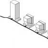
At the same time, switching equipment for Infiniband is quite expensive. And as mentioned above, the classical star as a topology computer network- Not the best choice.
However, InfiniBand hosts can be connected to each other directly, without a switch. Then, for example, this option becomes quite interesting: a cluster of two computers connected via infiniband. Such a supercomputer can easily be assembled at home.
How many video cards do you need?
In the most powerful supercomputer of our time, Cray Titan, the ratio of processors to “video cards” is 1:1, that is, it has 18688 16-core processors and 18688 Tesla K20X.In Tianhe-1A, a Chinese xeon-based supercomputer, the relationship is as follows. Two six-core processors for one Nvidia M2050 video card (weaker than K20X).
We will accept this attitude for our assemblies as optimal (because it is cheaper). That is, 12-16 processor cores per GPU. In the table below, practically possible options are indicated in bold, and the most successful ones from my point of view are underlined.
| GPU | Cores | 6-core CPU | 8-core CPU | 12-core CPU | 16-core CPU | |||||
| 2 | 24 | 32 | 4
|
5 |
3
|
4
|
2
|
3
|
2
|
2
|
| 3 | 36 | 48 | 6 |
8 |
5 |
6 |
3
|
4
|
2
|
3
|
| 4 | 48 | 64 | 8 |
11 |
6 |
8 |
4
|
5 |
3
|
4
|
If the system is already established relationship processors/video cards will be able to take on board additional computing devices, then we will add them to increase the power of the assembly.
So how much does it cost
The options presented below are a supercomputer chassis without RAM, hard drives and software. All models use the AMD HD 7970 GHz Edition video adapter. It can be replaced with another one, as required by the task (for example, xeon phi). Where the system allows, one of the AMD HD 7970 GHz Edition is replaced with a three-slot AMD HD 7990 Devil 13.Option 1 on Supermicro H8QGL-6F motherboard

| Motherboard | Supermicro H8QGL-6F | 1 | 1200 | 1200 |
| CPU | AMD Opteron 6344 | 4 | 500 | 2000 |
| CPU Cooler | Thermaltake CLS0017 | 4 | 40 | 160 |
| Case 1400W | SC748TQ-R1400B | 1 | 1000 | 1000 |
| Graphics accelerator | AMD HD 7970 GHz Edition | 3 | 500 | 1500 |
| 5860 |
Theoretically, the performance will be about 12 Tflops.
Option 2 on the TYAN S8232 motherboard, cluster

This board does not support Opteron 63xx, so 62xx is used. In this option, two computers are connected into a cluster via Infiniband x4 DDR using two cables. Theoretically, the connection speed in this case will be limited to the speed of PCIe x8, that is, 32Gb/s. Two power supplies are used. How to coordinate them with each other can be found on the Internet.
| Quantity | Price | Sum | ||
| Motherboard | TYAN S8232 | 1 | 790 | 790 |
| CPU | AMD Opteron 6282SE | 2 | 1000 | 2000 |
| CPU Cooler | Noctua NH-U12DO A3 | 2 | 60 | 120 |
| Frame | Antec Twelve Hundred Black | 1 | 200 | 200 |
| power unit | FSP AURUM PRO 1200W | 2 | 200 | 400 |
| Graphics accelerator | AMD HD 7970 GHz Edition | 2 | 500 | 1000 |
| Graphics accelerator | AX7990 6GBD5-A2DHJ | 1 | 1000 | 1000 |
| Infiniband adapter | X4 DDR Infiniband | 1 | 140 | 140 |
| Infiniband cable | X4 DDR Infiniband | 1 | 30 | 30 |
| 5680 (per block) |
For a cluster of such configurations you need two and their cost will be $11360 . Its power consumption at full load will be about 3000W. Theoretically, performance will be up to 31Tflops.
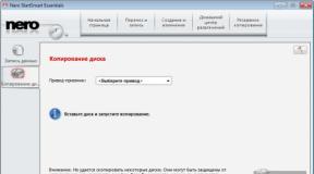
This article will show you how to build a Server 2012 failover cluster with two nodes. First, I'll list the prerequisites and provide an overview of the hardware environment, network, and storage settings. It will then detail how to extend Server 2012 with failover clustering capabilities and use Failover Cluster Manager to configure a two-node cluster.
IN Windows Server There are so many innovations in 2012 that it’s hard to keep track of them all. Some of the most important building blocks of the new IT infrastructure involve improvements in failover clustering. Failover clustering began as a technology to protect mission-critical applications required for production operations, such as Microsoft SQL Server and Microsoft Exchange. But subsequently, failover clustering evolved into a high availability platform for a number of services and Windows applications. Failover clustering is part of the foundation of Dynamic Datacenter and technologies such as live migration. With Server 2012 and new enhancements Server protocol Message Block (SMB) 3.0 extends the scope of failover clustering to provide continuously available file resources with shared access. An overview of the functionality of failover clustering in Server 2012 is given in the article “New features of failover clustering in Windows Server 2012” published in the same issue of the magazine.
Failover Clustering Prerequisites
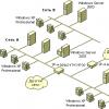
To build a two-node Server 2012 failover cluster, you need two computers running Server 2012 Datacenter or Standard editions. These can be physical computers or virtual machines. Clusters with virtual nodes can be built with using Microsoft Hyper-V or VMware vSphere. This article uses two physical servers, but the steps for setting up a cluster for physical and virtual nodes are the same. Key Feature is that the nodes must be configured identically so that the backup node can run workloads in the event of a failover or live migration. The components used in the Server 2012 test failover cluster are shown in the figure.
A Server 2012 failover cluster requires shared storage such as iSCSI, Serially Attached SCSI, or Fiber Channel SAN. Our example uses an iSCSI SAN. The following features of this type of storage should be kept in mind.
- Each server must have at least three network adapters: one to connect the iSCSI storage, one to communicate with the cluster node, and one to communicate with the external network. If you plan to use a cluster for live migration, then it is useful to have a fourth network adapter. However, live migration can also be performed through an external network connection- it will just run slower. If servers are used for Hyper-V-based virtualization and server consolidation, then additional network adapters are needed to transmit network traffic virtual machines.
- It is always better to work on fast networks, so the speed of the iSCSI communication channel should be at least 1 GHz.
- The iSCSI target must conform to the iSCSI-3 specification, specifically providing persistent redundancy. This is a mandatory requirement of live migration. Almost all storage vendors have hardware that is iSCSI 3 compliant. If you want to set up a cluster in a lab environment at a low cost, be sure to ensure that the iSCSI target software meets iSCSI 3 and persistent redundancy requirements. Older versions of Openfiler do not support this standard, but new version Openfiler with Advanced iSCSI Target Plugin (http://www.openfiler.com/products/advanced-iscsi-plugin). Besides, free version StarWind iSCSI SAN Free Edition from StarWind Software (http://www.starwindsoftware.com/starwind-free) is fully compatible with Hyper-V and live migration. Some Microsoft versions Windows Server can also function as an iSCSI target that is compliant with iSCSI 3 standards. Server 2012 includes an iSCSI target. Windows Storage Server 2008 R2 supports iSCSI target software. In addition, you can download Microsoft program iSCSI Software Target 3.3 (http://www.microsoft.com/en-us/download/details.aspx?id=19867), which works with Windows Server 2008 R2.
For more information about configuring iSCSI storage for a failover cluster, see the sidebar "ISCSI Storage Configuration Example." More details about the requirements for failover clustering are described in the article “Failover Clustering Hardware Requirements and Storage Options” (http://technet.microsoft.com/en-us/library/jj612869.aspx).
Adding Failover Clustering Features
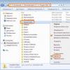
The first step to creating a two-node Server 2012 failover cluster is to add the failover cluster component using Server Manager. Server Manager automatically opens when you log in to Server 2012. To add a failover cluster feature, select Local Server and scroll down to the ROLES AND FEATURES section. From the TASKS drop-down list, select Add Roles and Features, as Figure 1 shows. This will launch the Add Roles and Features Wizard.
The first page to open after launching the wizard is the Before you begin welcome page. Click Next to go to the installation type selection page, which asks if you want to install the component on local computer or in service Remote Desktop. For this example, select the Role-based or feature-based installation option and click Next.
On the Select destination server page, select the server on which you want to install the failover cluster features. In my case it's local server named WS2012-N1. With your local server selected, click Next to go to the Select server roles page. IN in this example The server role is not installed, so click Next. Or you can click the Features link in the left menu.
On the Select features page, scroll down the list of features to Failover Clustering. Click in the box in front of Failover Clustering and you will see a dialog box listing the various components that will be installed as part of that component. As Figure 2 shows, by default the wizard will install failover cluster management tools and the failover cluster module for Windows PowerShell. Click the Add Features button to return to the feature selection page. Click Next.
The Confirm installation selections page will show the failover cluster feature along with management tools and a PowerShell module. You can go back and make any changes from this page. When you click the Install button, the actual installation of the components will begin. Once the installation is complete, the wizard will complete and the Failover Cluster feature will appear in the ROLES AND FEATURES section of Server Manager. This process must be completed on both nodes.
Testing a Failover Cluster
The next step after adding the failover cluster feature is to review the settings of the environment in which the cluster is created. Here you can use the Validate Settings Wizard in Failover Cluster Manager. This wizard checks the hardware settings and software all nodes in the cluster and reports any problems that may interfere with the organization of the cluster.
To open Failover Cluster Manager, select the Failover Cluster Manager option from the Tools menu in Server Manager. In the Management area, click the Validate Configuration link, as Figure 3 shows, to launch the Validate Configuration Wizard.
.jpg) |
| Screen 3: Launching the Verify Configuration Wizard |
First, the wizard's welcome page is displayed. Click Next to go to the server selection or Cluster page. On this page, enter the node names of the cluster that you want to check. I specified WS2012-N1 and WS2012-N2. Click Next to display the Testing Options page, where you can select specific test suites or run all tests. At least for the first time, I recommend running all the tests. Click Next to go to a confirmation page that shows the tests that are running. Click Next to begin the cluster testing process. During testing, the version is checked operating system, network and storage settings for all cluster nodes. A summary of the results is displayed after the test is completed.
If the validation tests are successful, you can create a cluster. Figure 4 shows the summary screen for a successfully verified cluster. If errors are found during the check, the report will be marked yellow triangle(warnings) or a red "X" for serious errors. Warnings should be read but can be ignored. Serious errors must be corrected before creating a cluster.
As a result, the cluster creation wizard will be launched, the work of which starts from the welcome page. Click Next to go to the Server Selection page, which Figure 6 shows. On this page, enter the names of all nodes in the cluster, then click Next.
On the Access Point for Administering the Cluster page, you must specify the name and IP address of the cluster, which must be unique on the network. As you can see in Screen 7, my cluster name is WS2012-CL01 and the IP address is 192.168.100.200. When using Server 2012, the cluster IP address can be assigned via DHCP, but I prefer a statically assigned IP address for my servers.
After entering your name and IP address, click Next to see a confirmation page (Figure 8). On this page you can verify the settings made when creating the cluster. You can go back and make changes if necessary.
After clicking the Next button on the confirmation page, a cluster is formed on all selected nodes. The progress page shows the wizard steps in the process of creating a new cluster. When completed, the wizard will display a summary page with the settings for the new cluster.
The New Cluster Wizard automatically selects the quorum storage, but it often selects a different quorum disk than the administrator would like. To check which disk is used for quorum, open Failover Cluster Manager and expand the cluster. Then open the Storage node and click the Disks node. The disks available in the cluster will be shown in the Disks panel. The disk selected by the wizard for cluster quorum will be listed in the Disk Witness in Quorum section.
In this example, Cluster Disk 4 was used for quorum. Its size is 520 MB, slightly larger than the minimum value for quorum of 512 MB. If you want to use a different disk for cluster quorum, you can change the cluster settings by right-clicking the cluster name in Failover Cluster Manager, selecting More Actions, and then selecting Configure Cluster Quorum Settings. This will display the Quorum Configuration Wizard, which allows you to change the cluster quorum settings.
Configuring Cluster Shared Volumes and Virtual Machine Roles
Both nodes in my cluster have the Hyper-V role because the cluster is designed for highly available virtual machines that provide live migration. To make live migration easier, you next need to configure Cluster Shared Volumes (CSV). Unlike Server 2008 R2, Cluster Shared Volumes are enabled by default in Server 2012. However, you still need to specify which storage to use for Cluster Shared Volumes. To enable CSV on an available disk, expand the Storage node and select the Disks node. Next, select the cluster disk that you want to use as CSV and click the Add to Cluster Shared Volumes link in the Actions panel of Failover Cluster Manager (Figure 9). The Assigned To field for this cluster disk changes from Available Storage to Cluster Shared Volume, as Figure 9 shows.
At this time, the Failover Cluster Manager configures the cluster disk storage for the CSV, specifically adding a mount point to system disk. In this example, Cluster Shared Volumes are enabled on both Cluster Disk 1 and Cluster Disk 3 with the following mount points added:
* C:ClusterStorageVolume1 * C:ClusterStorageVolume2
At this stage, a two-node Server 2012 cluster has been built and Cluster Shared Volumes have been enabled. You can then install clustered applications or add roles to the cluster. In this case, the cluster was created for virtualization, so we add the virtual machine role to the cluster.
To add a new role, select the cluster name in the Failover Cluster Manager navigation pane and click the Configure Roles link in the Actions pane to launch the High Availability Wizard. Click Next on the Welcome page to go to the role selection page. Scroll down the list of roles until you see the virtual machine role, as Figure 10 shows. Select the role and click Next.
The virtual machine selection page will list all the VMs on all nodes in the cluster, as Figure 11 shows. Scroll through the list and select the virtual machines that you want to provide high availability. Click Next. Once you confirm your selection, click Next to add the virtual machine roles to the Failover Cluster Manager.
Example of iSCSI storage configuration
For fault tolerant Windows cluster Server 2012 requires shared storage, which can be iSCSI, Serially Attached SCSI, or Fiber Channel SAN. This failover cluster uses a Channel SAN.
First, three LUNs were created on the iSCSI SAN. One LUN was created for the cluster quorum disk (520 MB). The other LUN is for 10 virtual machines and is 375 GB in size. The third LUN is dedicated to a small test virtual machine. All three LUNs are in NTFS format.
After the LUNs were created, iSCSI Initiator was configured on both Server 2012 nodes. To add iSCSI targets, iSCSI Initiator was selected from the Tools menu in Server Manager. On the Discovery tab, I clicked the Discover Portal button. As a result, the Discover Portal dialog box appeared, where the IP address (192.168.0.1) and iSCSI port (3260) of the SAN network were entered.
I then went to the Targets tab and clicked the Connect button. In the Connect To Target dialog box, I entered the target iSCSI SAN name. It was obtained from the SAN properties. The name depends on the SAN provider, the domain name, and the names of the LUNs created. In addition to the target name, I set the Add this connection to the list of Favorite Targets mode.
Once the iSCSI setup is complete, these LUNs appear in the Targets tab of the iSCSI Initiator. To automatically mount LUNs when Server 2012 starts, I made sure they are listed in the Favorite Targets tab, as shown in Screen A.
.jpg) |
| Screen A: Configuring iSCSI Initiator |
Finally, letter names were assigned to the LUNs using the Disk snap-in Management console Microsoft Management (MMC). I selected Q for the quorum disk and W for the disk used for virtual machines and Cluster Shared Volumes (CSV). When assigning letter symbols, you must first assign them on the same node. Then you need to take the disks offline and make similar assignments on the second node. The results of assigning drive letters for a single node are shown in Screen B. When you create a cluster, the drives will be shown as available storage.
Read also...
- How to check your phone's certification
- Installing CAB and MSU files for Windows updates manually
- Smartphone Samsung GT I8160 Galaxy Ace II: reviews and specifications The main camera of a mobile device is usually located on the back of the body and is used for photo and video shooting
- How to work in the Sony Vegas program (basics) How to work in the Sony Vegas program