Setting up secure wireless networks MikroTik hAP AC. Setting up MikroTik for a point-to-point connection Setting up a computer network card
Quantity wireless devices growing rapidly, constantly increasing the requirements for bandwidth network and its coverage.
There are now enough solutions on the market to create a large wireless network in both a small private house and a large country cottage, starting with Luma, Eero, and ending with and.
Some solutions are easy to set up and high in price, others provide great opportunities, but require a good base for customization. In particular, we are talking about Mikrotik products, which are distinguished by an excellent combination of high reliability, great functionality and quite affordable cost. At the same time, Mikrotik will be difficult to understand settings for the vast majority of home users, which increases the level of entry and severely limits the actual use of Mikrotik-based systems at home.
Despite the drawback described above, once you set up Mikrotik, you can forget about it for months, and even years. Mikrotik equipment is able to work for six months or even more without rebooting, saving you time and nerves.
As part of this publication, we will show and tell you how to create and configure based on Mikrotik reliable network with excellent wireless coverage for a large apartment, private house or small office with a minimum of wires.
Router selection
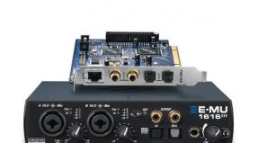
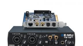
A router (model RB960PGS) is well suited to create a high-performance network. The presence of an SFP slot allows you to connect to an Internet provider using optics, in addition, the device is equipped with 5 gigabit interfaces.
If SFP is not used, Internet connection can be made using the first RJ-45 network interface, which also supports PoE In. The remaining 4 interfaces support PoE Out, which allows you to power several access points from them, but no more than 4.
In practice, a wired network is also almost always used, so at least one port will need to be allocated for a wired local network, in total we will have 3 PoE ports at our disposal, which is enough for a medium-sized private house.
If home use is expected, any gigabit switch of any brand will do before the expansion of the wired network. At the same time, if you plan to use VLAN and other exotics, you will need a managed switch, or at least Easy-Smart, we advise you to pay attention to a managed switch.
In the case when you need to power more than 3 access points, you can purchase a managed switch with PoE -. Please note that buying an additional PoE switch will only be justified if you will power 2-4 additional access points from it. Otherwise, buying a switch to power just one point will be a waste of money.
For 100 Mbps networks, more affordable PoE router models are suitable:
It is not necessary to purchase PoE-enabled devices, but in this case you will need to assemble a small communication box and place all the injectors and adapters in it.
Access point selection
In the case of access points, the choice is much wider. Below we have selected the most interesting offers, and they are sorted in ascending order of price.
Please note that the Groove 52 model (RBGroove52HPn) will not fit, because comes with a level 3 license that does not allow the use of AP mode.
You probably have a legitimate question, what does hAP ac lite do in this table? Everything is simple. First, he has PoE support, which allows you to power it remotely. Secondly, the router provides the possibility of wall mounting. Thirdly, it is, of course, 802.11ac support and the price is only $45.
Thanks to the combination of these parameters, it can be used as a Dual-Band access point with the functionality of an additional switch. The only limitation is the speed of network interfaces of 100 Mbps.
Point GrooveA 52 is highlighted separately, because it is equipped with a powerful radio module and is suitable for outdoor use when a very large area needs to be covered. Please note that the device can only operate in one band at a time - either 2.4 GHz or 5 GHz. Range selection is carried out manually in the control panel.
OmniTIK and Metal are also missing from the table, due to the price/feature ratio. These solutions are more suitable for use in commercial networks.
Most best option to build a network at home -, and. Moreover, wAP and wAP ac can be used outside the premises.
The older wAP ac model is equipped with a gigabit network interface to ensure high throughput, simultaneous operation in two bands with a channel rate of 300 and 1300 Mbps for 2.4 and 5 GHz is supported, respectively.

Actually, using the example of wAP and wAP ac in conjunction with the hEX PoE switch, we will consider building a home wireless network.
Connecting and configuring the gateway
hEX PoE will act as the main router providing access to the Internet for clients. As expected, the gateway will issue IP addresses for other devices, while the DHCP server will be disabled on the access points themselves.
We connect the device and log in to the control panel.

The setup process will be considered using the default settings as an example, in order to simplify the process as much as possible for novice Mikrotik users.


The standard configuration is quite suitable for us, the only thing you need is to configure the type of connection to the provider's network and select the ETH1 port (twisted pair) or SFP (optics)

For convenience, we change the IP devices and settings local network for more familiar ones - 192.168.0.1/24.
Please note that we deliberately raised the DHCP pool up, which is not necessary at all. Personally, it’s easier for me to use statics and MAC: IP binding at the bottom, and issue IP for other clients in the “upper” part.
Be sure to change the name of the device, in our case it will be “GATEWAY” (gateway), in the future, with a large number of devices, it will be much easier for you to navigate by name than by IP.

Applying the settings. After that, Winbox will become inaccessible, on some PCs you will need to reconnect to the network by poking the cable so that the network receives a new IP.

It's good practice to go to IP - DHCP Server - Networks and manually add our router's IP as a DNS server for clients receiving DHCP settings. Mikrotik has its own DNS functionality, so using the provider's DNS on clients does not make sense.
By the way, you can immediately specify NTP, you can easily raise it on Mikrotik itself. If you replace time.windows.com with Mikrotik's IP in static DNS records, machines running Windows will be able to take the exact time from the main gateway without additional settings. Read more in a separate post, link above.

Don't forget to update the gateway to latest version RouterOS, in our case, this is an update from 6.36.1 to 6.38.1. The device will reboot to update.
The general configuration of the gateway is now complete. Creating a new user, changing the password, disabling unnecessary services and other Mikrotik security settings is a topic for a separate publication, so we will not dwell on this.
At this stage, you can connect access points to the router.
Connecting access points to a router
Both points will be powered by PoE from the main router. This approach will allow us to overload devices programmatically at a distance, and also get rid of extra wires.
In practice, connecting points is best done in stages, since all wAPs have an open network and a standard password.
We will connect both points at once, because For advanced user the process only takes a couple of minutes.

The usual Mikrotik wAP Access Point was powered by PoE without any problems, but for wAP ac, I had to select the “forced on” PoE mode in the port settings. You can read more about priorities and PoE Out settings in general in.
As you can see, in idle mode, wAP consumes only 1.1 W, and the older brother wAP ac consumes 3.3 W.

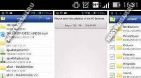
In the IP - DHCP Server - Leases section, you can make sure that both access points have received an IP address.
Let's move on to the next step of the setup.
Mikrotik wAP connection
Both wAPs are configured by connecting to the open wireless network of the access point. For these purposes, a netbook, laptop or PC with wireless adapter. In our case, it will be a netbook.

As you can see, the netbook successfully detected all 3 networks. Why three and not two? The fact is that wAP ac has one network at 2.4 GHz, the second at 5 GHz.
MikroTik-5EDCC7 is our Mikrotik wAP, MikroTik-7D550D and MikroTik-7D550E networks are Mikrotik wAP ac, which is easy to identify by the network name (the name differs by the last character).
We will start the setup from the simplest point, it is faster and will allow you to understand how to set up a dual-band point.

After connecting to the MikroTik-5EDCC7 wireless network, Winbox will detect the device with standard IP 192.168.88.1


We accept the standard configuration. As you can see, the device works in routing mode, which is why it is not possible to connect to it via a cable.

Switch the point to bridge mode (Bridge = bridge), this will make the device completely transparent. Set the “Address Acquisition” option to “Automatic”, i.e. The IP device will receive from the DHCP server. If you wish, you can implement a static IP, but more on that later, we will implement it a little differently.
“Address Source” should be set to “Any”, otherwise, if you select the seemingly logical “Ethernet”, the device will have IP 0.0.0.0 and you simply will not connect to it. If everything is done correctly, the device will receive the network settings.
As before, we change the name of the device.
Connecting Mikrotik wAP ac
All of the above actions are repeated for a new point, as well as for each subsequent one that will be added to the network.


If everything is done correctly, all three devices will be visible in Winbox.

And, of course, do not forget to update RouterOS on all network devices.

Setting up a wireless network in Mikrotik wAP
First, let's set up a wAP access point.

In the Wireless - Interfaces section, open the properties of the wireless interface.
Personally, I am a supporter of "Advanced Mode" (advanced mode), if the number of options scares you - you can use "Simple Mode". Switching between modes is carried out at any time in the right part of the settings window.
On the current window, we are interested in “Freq. Usage...". After clicking on this button, a new window will open in which you should click "Start". The system will start scanning the channels and you will be able to see the channel usage level in real time.
As you can see, 2442-2452 MHz is used, so it is best to work in the 2412-2432 MHz band. At the same time, one should not forget that when using wide channels of 40 MHz, the number of non-overlapping channels is 3.

When configuring the wireless interface, I prefer to explicitly specify 2GHz-only-N, which sets the mode to 802.11n. if you have old devices without support for the new standard, use mixed modes.
We set the channel width to "20/40 Ce", you can also specify "20/40 eC". The index eC and Ce indicate where it is necessary to expand the range, in relation to the main channel. eC - downward expansion, Ce - upward expansion. Thus, if you select the first channel, you can only expand it upwards, in the case of the last channel, the situation is reversed, it can only be expanded downwards.
SSID is the name of the wireless network. If you have access points that support 5 GHz, you can explicitly specify the suffixes 2G and 5G to help distinguish the bands. If this is not done, on the client, instead of two networks, only one will be visible in the list, and the connection will be made according to the adapter's priorities (Prefer 2G/Prefer 5G).
WPS should be disabled if not used.
"Frequency Mode" set "regulatory-domain", and "Country" - "ukraine". This setting will allow you not to violate regional restrictions on the use of the radio frequency resource.
"WMM Support" can be selected "enabled". This is a special QoS add-on that allows you to increase the priority of multimedia traffic.
Go to the "Advanced" tab. For the option "Hw. Protection Mode" select "rts cts". In short, this option helps to avoid conflicts when clients connected to the point do not see each other and cannot agree on the sequence of data transfer.
For "Adaptive Noise Immunity" set "ap and client mode". Again, in short, this option allows you to activate a special noise filtering algorithm, created by the point and/or the client, for example, multiple signal reflections from the walls. Please note that the option will only work on adapters with Atheros chips.

On the HT tab, check the "Tx / Rx Chains" parameters, which should be checked everywhere. If the checkbox is not checked on one of the channels, the adapter will not be able to use it during operation.
Since we did not change the power parameters of the radio module, the default values will apply.

In this case, we are only interested in HT20-x and HT40-x. In fact, this is a kind of power reference for a particular radio module.
HT20 and HT40 indicate channel widths of 20 and 40 MHz, respectively. The number in the suffix is the MCS speed index for the 802.11n standard. The higher the number, the faster the speed. As you can see, for higher speeds, less power is used, and the higher the speed, the lower the power. Take this data into account if you decide to adjust the power of the wireless module in manual mode.
At the final stage, go to the "Security Profiles" tab (security profiles). In this section, you need to adjust the security profile. We select the "dynamic keys" mode, as well as the WPA2 and AES options. You can forget about WPA and TKIP forever (not to mention the outdated WEP), these security options have long been compromised and have loopholes that allow an experienced attacker to gain access to a wireless network protected by this method.
The network password is entered in the "WPA2 Pre-Shared Key" field. This completes the setup of the first point.
Setting up a wireless network in Mikrotik wAP ac
When configuring the second access point, we do everything in the same way as the first access point.

Don't forget that you need to scan the wireless network for each point, because the air conditions may vary depending on the location. If you want to trust automation, choose the "auto" channel, Mikrotik does a pretty good job of this task.

Remember to specify the exact same SSID for the new and each subsequent point as on the first device. This is necessary for automatic roaming of clients between APs.
The operating frequency can be specified the same, but only if the access points overlap slightly. Otherwise, the points will share the air among themselves, which will negatively affect the speed during simultaneous operation. It is best to use the "checkerboard" principle, i.e. alternate channels so that they don't overlap at all.
In the case of Dual-Band access points, there will be 2 interfaces in the Wireless Interfaces list, each configured separately.

The principle is the same, we scan the range and select the optimal frequency. If your 5745-5805 range is clean, we recommend using it. In our case, it is already "clogged" with local providers.
By the way, for experienced administrators, spectral-scan and spectral-history will be of interest. Both tools work through the terminal.


The following commands are used to call:
/interface wireless spectrum-scan
/interface wireless spectral-history
We decided on channels and frequencies.

For the 5 GHz band, we indicate the 5G suffix, it is not necessary to do this at all, as mentioned earlier.
The default channel width will be 20/40 MHz, but we know that 802.11ac can use 80 MHz channels and it is on them that it provides high speed.
For 80 MHz channels, the eCee add-on is used in various combinations, there are 4 of them in total, because an 80 MHz channel combines 4 x 20 MHz channels. The selection logic is the same as for 2.4 GHz.

We perform the settings in the same way as those made for previous point and the 2.4 GHz band. Don't forget to check Chains and adjust your security settings (profile).
Nuances of roaming on Mikrotik
In principle, this could be completed brief instructions, but there is one more nuance.

In practice, quite often there are cases when wireless networks intersect. In such cases, the client may stubbornly hang on the point with weak signal, even though he has a point with an excellent signal level “under his nose”.
Actually, an example of such a case is in the screenshot above. On the left, we can see that the phone is connected to a 5GHz network with good signal strength. After moving to another area, the smartphone still hangs on the 5 GHz network, despite the fact that the channel speed has dropped to 87 Mbps, and there is a 2.4 GHz network nearby with an excellent signal.
What to do in this case? You can switch the network manually if the networks different names, but you can also use the "file" and "crutches".

First of all, on all wireless interfaces, you must disable the "Default Authenticate" option. This is necessary in order to use the ACL functionality.

In the Access List tab (the section is still the same, Wireless), we create 2 rules.
First rule. Set the signal level range to -75...120 dBm, set the Authentication and Forward options. This rule will allow connection for clients whose signal level is at least -75 dBm.
Second rule. Set the range to -120...-76 dBm, disable the Authentication and Forward options. This rule will disable clients whose signal level drops below -76 dBm.
The Authentication option allows the connection, therefore, its absence prevents the connection. The Forward option enables data exchange between stations/clients. A forward can be useful in a protected home network, but in a public open network, data exchange between clients must be prohibited without fail for security purposes.
If desired, here you can also set up rules for the days of the week and time. For these purposes, below under the spoiler Time there are the necessary parameters.

After the ACL rules are created, in the Registration table you can see the list of authorized clients. Moreover, the comment for each client will contain a comment from the ACL rule (if it is set), which is very convenient.

We check the work on the smartphone. When the signal level deteriorates to -75 dBm, the device still holds on to the old point. As soon as the signal deteriorates to -76 dBm, the point automatically disconnects the client, after which the client connects to the strongest point.

However, this method not without flaws. The thing is that the points carry out a forced disconnection of the client, due to which the end client experiences a short-term disconnection. At best, it is ~2 seconds. A lot depends on the client hardware.
I set the signal level to -75 dBm only as an example, this is a more recommended level than a universal parameter “for any occasion”. In practice, it is sometimes necessary to use -80 dBm and below. In any case, the value is selected exclusively by experimental method right on the spot, based on the specific coverage and sensitivity of the client equipment.
Finally
Of course, there are many options for implementing a home wireless network on Mikrotik, starting with manual setting and ending with the use of CAPsMAN and even Mesh.
We have described a completely manual configuration option so that the end user understands “how it works”, moreover, this option does not require deep knowledge. In the same time, given configuration allows you to create a reliable wireless network that can work stably without your intervention.
Among the shortcomings, it is worth noting the need to separately configure all devices, which takes a little more time than when using CAPsMAN. When using multiple points, this option is quite suitable and provides good flexibility.
Internet for modern people, it has become not only an indispensable and necessary attribute, but also an object of first importance, replacing a large number of other things previously used. Therefore, high-quality and high-speed Internet is worth a lot. For building a wireless network you only need proven, reliable equipment and an integrator who will implement your project. Buy what you need wifi network equipment for your network free sale not so easy. Do not waste your time searching in vain, contact Internet shop site. With us you will find active and passive equipment in a wide range of world brands. Wi-fi equipment for restaurants and hotels, twisted pair for outdoor installation, optical cable, PON equipment, PON devices, OLT devices, CWDM equipment and much more are presented in our Mstream online catalog.
We cooperate only with trusted manufacturers of the IT market - Ubiquiti, Mikrotik, Cambium Networks, D-link, Hikvision, Furuno, Ajax, Ok-net, ICOM, Sailor, Zenitel, Cobham and that is why all equipment for radio communication, marine navigation, wireless or local network, presented in our store, meet the highest quality standards. Order wifi internet equipment it is possible both at retail and wholesale (we cooperate with Internet providers, integrators and resellers). For regular customers, the Mstream online store has a flexible system of discounts and payment delays. Prices wifi internet equipment will delight even retail customers. Our task is not only to develop ourselves, but also to help develop the business of our clients. Wi fi space in Ukraine is not yet so developed and busy, and our goal is the global integration of new technologies and developments in the Ukrainian technology market.
Buying from us equipment for wifi networks , you are guaranteed to receive very reliable, high-quality and durable solutions from the world's best manufacturers and brands of wireless technology in the most short time. Huge range and direct deliveries WiFi equipment from the manufacturer allow us, as a system integrator, to satisfy any projects of our clients - the creation of a local wi fi network. Professional consultants will provide full advice on choosing the right network equipment, taking into account individual projects and the wishes of the client, which will save your time and effort. Delivery of network equipment to all cities of Ukraine - Odessa, Kiev, Kharkiv, Kherson, Kryvyi Rih, Kropyvnytskyi, Nikolaev, Dnepropetrovsk, Zaporozhye, Vinnitsa, Chernihiv, Cherkassy, Poltava, Mariupol, Lviv, Ternopil, Kramatorsk, Novomoskovsk, as well as Transnistria, Tiraspol, Moldova (Moldova) and others.
Copying any information from the site without placing an active backlink is prohibited.
MikroTik's new device with 2G/3G/4G support is made in the design of wAP series devices, this is the company's first multi-band device, last year a solution with support for LTE only was already presented, which limited its scope.
This model will allow you to cover on your own the segment of both stationary - a small house outside the city, an apartment in the city, and mobile solutions such as a hot spot in minibus transport, buses, intercity buses and, of course, a personal and company car.
For transport, a power connector is specially integrated on the board, a constant plus and a plus from the ignition, a cable with a connector is included in the package

Opening the cover will give you access to the power connectors, Ethernet, indicators, SIM card slot and reset button

Having removed the case, we see the module wifi antennas and two LTE antennas similar in size to ZyXEL MAX-206M2

Powered by PoE technology (8-30V), DC power (8-30V) and vehicle power (8-30V) are available

miniPCIe 2G/3G/4G R11e-LTE module, 2 x U.FL (Ultra Miniature Coaxial Connector Receptacle) Male connectors on top

Module specification:
2G Multislot Classes for GPRS/EGPRS
| Multislot class | Downlink TS | Uplink TS | Active TS |
|---|---|---|---|
| 12 | 4 | 4 | 5 |
3G Category 14 (21Mbps Downlinks, 5.76Mbps Uplinks)
| Evolved HSDPA User Equipment (UE) categories | ||||||
|---|---|---|---|---|---|---|
| Category | Release | Max. number of HS-DSCH codes (per cell) |
Modulation | MIMO, Multi-Cell | code rate at max. Data rate |
Max. Downlink Speed (Mbit/s) |
| 14 | 7 | 15 | 64-QAM | .98 | 21.1 | |
LTE Category 4 (150Mbps Downlink, 50Mbps Uplink)
| E UTRA Band |
duplex- mode |
ƒ (MHz) |
common name | Included in (subset of) Band |
Uplink (UL) BS receive UE transmit (MHz) |
Downlink (DL) BS transmit UE receive (MHz) |
Duplex spacing (MHz) |
Channel bandwidths (MHz) |
|---|---|---|---|---|---|---|---|---|
| 1 | FDD | 2100 | IMT | 65 | 1920 – 1980 | 2110 – 2170 | 190 | 5, 10, 15, 20 |
| 2 | FDD | 1900 | PCS blocks A-F | 25 | 1850 – 1910 | 1930 – 1990 | 80 | 1.4, 3, 5, 10, 15, 20 |
| 3 | FDD | 1800 | DCS | 1710 – 1785 | 1805 – 1880 | 95 | 1.4, 3, 5, 10, 15, 20 | |
| 7 | FDD | 2600 | IMT-E | 2500 – 2570 | 2620 – 2690 | 120 | 5, 10, 15, 20 | |
| 8 | FDD | 900 | E-GSM | 880 – 915 | 925 – 960 | 45 | 1.4, 3, 5, 10 | |
| 20 | FDD | 800 | EU Digital Dividend | 832 – 862 | 791 – 821 | −41 | 5, 10, 15, 20 | |
| 38 | TDD | 2600 | IMT-E (Duplex Spacing) | 41 | 2570 – 2620 | N/A | 5, 10, 15, 20 | |
| 40 | TDD | 2300 | 2300 – 2400 | N/A | 5, 10, 15, 20 | |||
The reverse side of the board has a SIM card slot on it.


Equipment

Device advantages
- The most affordable modem 2G 3G 4G connected via miniPCIe slot in the system is visible as usb, switching time between ranges is 15 seconds
- Built-in multi-band 4.5dBi MIMO antennas
- unlike the wAP LTE 2nD donor board, a heatsink is installed on the chipset
- there is an indication of the signal level, the sensitivity is set programmatically in the System - LEDs section
- Car power connector included
- the lock bolt for the cover and the key are included, the bolt is equipped with a spring, there is no need to catch it when unscrewing
Cons of the device
- Inconvenient Sim slot is missing a return spring - you can get a SIM card by disassembling the device or using tweezers
UPDATES
MikroTik's product range has new accessories for retrofitting the wAP LTE kit with an external panel antenna:
- ACSMAUFL cables - ACSMAUFL - pigtail U.fl-SMA - 2 pcs
- mANT LTE 5o - MTAO-LTE-5D-SQ - 5dBi LTE antenna
- SMASMA - cable assembly 1m SMA male - SMA male - 2 pcs

Performance testing of different versions of ROS on the example of the Beeline operator
Factory default version ROS 6.39.2


Latest Release candidate version ROS 6.43.14


The latest version of Bugfix only ROS is 6.40.8


There is no striking difference in speeds, release candidate ROS 6.43.14 gives a higher speed, but this can be attributed to measurement error
Settings
UPDATE It is best not to touch the modem settings, the modem automatically connects to the network faster, the only thing worth unchecking GSM (GPRS / EGPRS class 12) we do not need speed in the current sense is not there.
In the manual "bands" selection mode, the modem connects to the operator's network much longer
Changes since RouterOS 6.41:

APN profiles
Parameter apn changes now in the LTE - apn profile tab:
/interface lte apn add name=profile1 apn=internet authentication=chap password=web user=web Example for Yota operator /interface lte apn add name=profile1 apn=yota.ru
Select a profile for the current LTE connections:
/interface lte set apn-profiles=profile1
For the web interface of USB modems, the selection of presets occurs automatically by linking the profile to the operator, Mikrotik such functionality is not yet available
Passthrough
Starting with RouterOS v6.41, some LTE interfaces support the LTE Passthrough feature, where the IP configuration is applied directly to the client device. In this case, the modem's firmware is responsible for configuring the IP, and the router is only used to configure the modem's parameters - APN, network technologies, and IP type. In this configuration, the router will not receive an IP configuration from the modem. An LTE Passthrough modem can pass both IPv4 and IPv6 addresses if supported by the modem. Some modems support multiple APNs, where you can forward traffic from each APN to a specific router interface.
Passthrough will only work for one host. The router will automatically detect the MAC address of the first packet it receives and use it for Passthrough. If there are multiple hosts on the network, you can block Passthrough for a specific MAC. On a host on the network where Passthrough provides an IP address, a DHCP client must be enabled on that interface. Please note that it will not be possible to connect to an LTE router through a public IP address or from a host that is used by the passthrough. For configuration purposes, it is suggested to create an additional connection to the LTE router per host. For example, a vlan interface between an LTE router and a host.
Let's configure Passthrough on the ether1 interface:
/interface lte apn add apn=apn1 passthrough-interface=ether1 /interface lte set lte1 apn-profiles=apn1
Let's configure Passthrough on the ether1 interface for host 00:11:22:33:44:55:
/interface lte apn add apn=apn1 passthrough-interface=ether1 passthrough-mac=00:11:22:33:44:55 /interface lte set lte1 apn-profiles=apn1
Binding R11e-LTE to base station sector
Using the following command in terminal
/interface lte info lte1 once
Get modem status:
> /interface lte info lte1 once
pin status: no password required
functionality: full
manufacturer: "Mikrotik"
model: "R11e-LTE"
revision: "MikroTik_CP_2.160.000_v001"
current-operator: 25099
lac: 578
current-cellid: 200005126
phy-cellid: 74
access technology: Evolved 3G (LTE)
session-uptime: 1h33m38s
imei:
earfcn: 3300 (band 7, bandwidth 10Mhz)
rsrp: -90dBm
rsrq: -10dB
sinr: 5dB
cqi: 15
of the variables we need phy-cellid: 74, earfcn: 3300 (band 7, bandwidth 10Mhz) we will continue to work with them.
Using these acquired variables, you can send an AT command to the modem to lock on the BS sector in the following format:
AT*Cell=
To block the modem in LTE mode and the previously used BS sector, use the following AT command:
/interface lte at-chat lte1 input="AT*Cell=2,3,3300,74"
Unfortunately, after rebooting the device or resetting the modem, all set locks are lost.
If you wish, you can always write a script that will automatically prescribe the same parameters
Default settings or default settings
can be output to the terminal with the following command, it is better to output this via ssh
/system default-configuration print
classic configuration export option, manufacturer uses biridge address lists and static dns
#| LTE CPE Router with wireless AP: #| * lte interface connected to providers network (WAN por> #| * WAN port is protected by firewall and enabled DHCP cl> #| wlan1 Configuration: #| mode: ap-bridge; #| band: 2ghz-b/g/n; #| ht-chains: 0,1; #| ht-extension: 20/40mhz-Ce; #| LAN Configuration: #| IP address 192.168.88.1/24 is set on bridge (LAN por> #| DHCP Server: enabled ; #| DNS: enabled; #| WAN (gateway) Configuration: #| gateway: lte1 ; #| ip4 firewall: enabled; #| NAT: enabled; /interface lte set [ find ] add-default-route=yes default- route-distance=2 mac-address=00:00:00:00:00:00 name=lte1 use-peer-dns=yes /interface bridge add admin-mac=E4:8D:8C:3B:1C:BA auto -mac=no comment=defconf name=bridge /interface wireless set [ find default-name=wlan1 ] band=2ghz-b/g/n channel-width=20/40mhz-Ce disabled=no distance=indoors frequency=auto mode =ap-bridge ssid=MikroTik-000000 /ip neighbor discovery set lte1 discover=no /interface list add comment=defconf name=WAN add comment=defconf name=LAN /interface wireless security-profiles set [ find default=yes ] supplicant- identity=MikroTik /ip pool add name=default-dhcp ranges=192.168.88.10-192.168.88.254 /ip dhcp-server add address-pool=default-dhcp disabled=no interface=bridge name=defconf /interface bridge port add bridge= bridge comment=defconf interface=ether1 add bridge=bridge comment=defconf interface=wlan1 /interface list member add comment=defconf interface=bridge list=LAN add comment=defconf interface=lte1 list=WAN /ip address add address=192.168.88.1 /24 comment=defconf interface=bridge network=192.168.88.0 /ip dhcp-server network add address=192.168.88.0/24 comment=defconf gateway=192.168.88.1 /ip dns set allow-remote-requests=yes /ip dns static add address=192.168.88.1 name=router.lan /ip firewall filter add action=accept chain=input comment="defconf: accept established,related,untracked" connection-state=established,related,untracked add action=drop chain=input comment="defconf: drop invalid" connection-state=invalid add action=accept chain=input comment="defconf: accept ICMP" protocol=icmp add action=drop chain=input comment="defconf: drop all not coming from LAN" in-interface-list=!LAN add action=accept chain=forward comment="defconf: accept in ipsec policy" ipsec-policy=in,ipsec add action=accept chain=forward comment="defconf: accept out ipsec policy" ipsec -policy=out,ipsec add action=fasttrack-connection chain=forward comment="defconf: fasttrack" connection-state=established,related add action=accept chain=forward comment="defconf: accept established,related, untracked" connection- state=established,related,untracked add action=drop chain=forward comment="defconf: drop invalid" connection-state=invalid add action=drop chain=forward comment="defconf: drop all from WAN not DSTNATed" connection-nat- state=!dstnat connection-state=new in-interface-list=WAN /ip firewall nat add action=masquerade chain=srcnat comment="defconf: masquerade" ipsec-policy=out,none out-interface-list=WAN /tool mac-server set [ find default=yes ] disabled=yes add interface=bridge /tool mac-server mac-winbox set [ find default=yes ] disabled=yes add interface=bridge
Quick Set is an automatic configuration wizard that helps quickly without diving into the depths fine tuning RoS, configure the router and start using it. Depending on the device, several templates may be available to you:
Safety
The default configuration no longer allows you to connect to the router from an external network, but protection is based only on a packet filter. Do not forget about setting a password for the admin user. So, in addition to filtering and password, I do the following:
Availability on external interfaces
I disable services that are not needed in the home network (and not in all non-home networks), and I limit the rest by scope, indicating the addresses from which you can connect to these services.
The next step is to limit the discovery of the router by searching for neighbors. To do this, you must have a list of interfaces where this protocol can work, let's configure it:
/interface list add exclude=dynamic name=discover
Let's add to the discovery list the interfaces on which we want the Neighbors Discovey protocol to work.
Now let's set up the protocol by specifying the discovery list in its settings:
In a simple, home configuration, the discovery list may contain interfaces on which the access protocol can run. MAC address, for situations where the IP is not available, so we will configure this function as well:
Now, the router will become "invisible" on external interfaces, which will hide information about it (not all of course) from potential scanners, and even deprive the bad guys of an easy opportunity to gain control over the router.
DDoS Protection
Now let's add some simple rules to the packet filter:
/ip firewall filter add action=jump chain=forward connection-state=new in -interface-list=ISP jump-target=anti-DDoS add action=jump chain=input connection-state=new in -interface-list=ISP jump -target=anti-DDoS add action=drop chain=forward connection-state=new src-address-list=BAN-DDoS add action=return chain=anti-DDoS dst-limit=15,15,src-address/10s add action=add-src-to-address-list address-list=BAN-DDoS address-list-timeout=1d chain=anti-DDoS add action=jump chain=input connection-state=new dst-port=22,8291 in -interface-list=ISP jump-target=anti-BruteForce-3 protocol=tcp add action=drop chain=forward connection-state=new src-address-list=BAN-BruteForce-3 add action=return chain=anti-BruteForce -3 dst-limit=4/1m,1,src-address/1m40s add action=add-src-to-address-list address-list=BAN-BruteForce-3 address-list-timeout=1d chain=anti-BruteForce -3
And put them after the defcon rule for the icmp protocol.
The result will be a 24-hour ban for those who try to open more than 15 new connections per second. Many or few 15 connections, the question is debatable, here you can choose the number yourself, I chose 50 for corporate use, and I get 1-2 such bans per day. The second group of rules is much tougher, blocks connection attempts to the ssh(22) and winbox(8291) ports, 3 attempts per minute, and rest for a day;). If you need to display DNS server to the Internet, then a similar rule can cut off DNS Amplification Attacks, but the solution is not ideal, and there are many false positives.
RFC 1918
RFC 1918 describes the allocation of address spaces for globally non-routable networks. Therefore, it makes sense to block traffic from / to such networks on the interface that looks to the provider, except in situations where the provider gives you a "gray" address.
/ip firewall address-list add address=10.0.0.0/8 list="RFC 1918" add address=172.16.0.0/12 list="RFC 1918" add address=192.168.0.0/16 list="RFC 1918" /ip firewall filter add action=drop chain=input comment="Drop RFC 1918" in -interface-list=WAN src-address-list="RFC 1918" add action=drop chain=forward comment="Drop RFC 1918" dst-address -list="RFC 1918" out-interface-list=WAN add action=drop chain=output comment="Drop RFC 1918" dst-address-list="RFC 1918" out-interface-list=WAN
Place these rules near the beginning and don't forget to add the interface facing the ISP to the WAN list.
UPnP
A rather controversial technology that allows applications to ask the router to forward ports through NAT, however, the protocol works without any authorization and control, this is simply not in the standard, and is often a point of decreasing security. Customize to your liking:
SIP Conntrack
Among other things, it is worth disabling the conntrack SIP module, which can cause VoIP to work inadequately, most modern SIP clients and servers do fine without it, and SIP TLS makes it completely useless.
Dynamic and Nested Interface Lists
This feature is a very recent addition (since 6.41) and is very handy. However, there is a nasty bug (I reported it, but it has not been fixed yet), the bottom line is that after the router is restarted, the firewall rules that use these lists do not work for interfaces included in child lists. It is treated by adding child lists. Automation is simple:
In the Sheduler, we write a script for the start event (lists of interfaces for a configuration with balancing):
/interface list set ISP1TUN include="" set ISP include="" set TUN include="" :delay 2 set ISP1TUN include=ISP1,TUN1 set ISP include=ISP1 set TUN include=TUN1
WiFi
In an urban environment, when the air is extremely noisy, it makes sense to abandon 40MHz channels, this increases the specific signal power on the channel, since a 40MHz channel is essentially two 20MHz channels.
Bridge & ARP
If your router distributes the Internet and gives DHCP settings to clients, it makes sense to set the arp=reply-only setting, and enable add-arp=yes in the DHCP Server
Such a setting will prevent you from setting the IP address manually, since the router will only agree to work with the MAC-IP pair that it issued itself.
P.S. article taken from here https://habrahabr.ru/post/353730/

CAPsMAN by MikroTik - a good low cost solution if you need unified wireless coverage over a large area. It can be a large house with 2-3 floors, an office space, a cafe, etc.
All points managed by CAPsMAN can be combined into a single network ( analogue of the UniFi network in Ubiquiti) with seamless roaming. It gives increased comfort Wi-Fi usage: If you and your smartphone or laptop move out of the coverage area of a single point managed by CAPsMAN, to the coverage area of another on the same controller, the connection will not drop and you will not need to reconnect.

If we talk specifically about seamless roaming, then it could be configured on MikroTik even before the advent of CAPsMAN by deploying a MESH network. Therefore, the main advantage of this controller is the ability to centrally configure access points and manage them from one device, which greatly facilitates the work of a network administrator. Also thanks CAPsMAN setting up a single seamless Wi-Fi coverage has become much easier, and therefore more accessible.

In this article, we will analyze how to install and configure the controller Mikrotik CAPsMAN, taking for example and .
Preliminary information on configuring CAPsMAN
Controller wireless points CAPsMAN (Controlled Access Point system Manager) is included in the standard installation package of the latest versions of RouterOS. MikroTik Access Points latest models- cAP-2nD, hAP Lite and others, fully support management with this software, and by updating RouterOS, you can use the controller on previously released devices.
CAPsMAN is installed on a router that will act as a central point management device, and it can be a router without a wireless module. To work on the router, RouterOS must be installed at least version 6.11. CAPsMAN v.2 works starting from RouterOS versionv6.22rc7. It is best, of course, to use the controller of the second version - it eliminates most of the shortcomings of the first.
Points connected to the controller (CAP, or Controlled Access Points) must have a license level of at least 4. T access points are connected to a router with CAPsMAN installed using a twisted pair, and can also be connected to each other in series in a chain (also using a twisted pair).
Router OS update
The first thing we need to do before setting up CAPsMAN is to update software devices.
Reset the router settings to factory settings:
RB2011UiAS-2HnD-IN can be reset both using the Reset button, which is located on the back of the device between the antennas (hold it until the green LED starts flashing and release), and using the jumper hole on the bottom of the router, located under the Reset button (insert a screwdriver into the hole, turn on the device, wait 10 seconds until the configuration is reset).
Mikrotik cAP-2nD reset to factory settings using the Reset button located to the left of Ethernet port. Hold it until the LEDs start flashing and release.
We go to the official site and download the appropriate firmware.
As you can see, the same one suits us for both devices - mipsbe, download it. We recommend flashing points using the netinstall program.

We connect RB2011UiAS-2HnD-IN to the computer for configuration.
We connected the cable to the ETH6 port, but you can connect to any port except the first one. Network settings computers must be pre-configured so that the router and the network card of the computer have addresses on the same subnet.
Devices IP address MikroTik by default - 192.168.88.1, login - admin, password - empty.
We start WinBox, we go to the router.
In the first window, reset the default configuration. If we logged in by IP, the winbox will turn off in this place, since we have reset the IP address of the router as well. We go again, at the poppy address.
To update, go to Files menu.
Open it up and drag we put our downloaded file into this window with new firmware.We confirm the update.

After the download of the file with the firmware is completed, go to the System menu and click the Reboot item.
The router will reboot and update the firmware. Please note that this can be a long process - 3-5 minutes, although in our case the reboot was fast. Do not turn off the power during the update process!
Check if the bootloader is updated correctly.
We go to the System - RouterBoard menu and check if the versions in the Current Firmware and Upgrade Firmware fields match. If not, click the button Upgrade and reboot the router (the screen was made during the cap-2nD update, the picture is similar on the router).

Setting up a router with a CapsMan controller
We configure RB2011UiAS-2HnD-IN in the QuickSet tab by setting the Ethernet mode and selecting Bridge mode, as in the screenshot:

We combine all the ports and channels of the WiFi device into a single bridge (so that the points connected both via WiFi and via a wired network can see each other).
To do this, go to the Interface tab and create a new one (plus on the top left), select bridge in the drop-down menu and give it a new name. We used an existing bridge and did not create a new one, but for personal convenience and ease of managing points, we recommend creating a separate interface.
Our bridge settings end up looking like this:

Settings on the Ports tab, all router interfaces are added here:

In the IP - Addresses menu, enter the address for the router (during the configuration, we assigned it the usual default address - 192.168.88.1).
Similarly, we update the access point Mikrotik cAP-2nD, we also combine its ports into bridge1, and prescribe the IP address (we assigned the address 192.168.88.28 to our "experimental" cAP-2nD).
In the simple case (we configured it this way), all points belong to the same subnet, but CAPsMAN can also be configured if the devices are on different subnets.
Activation of the CAPsMAN module
In the latest firmware, the module is activated by default (it is included in the wireless package), and in the menu at the top left there is always a CAPsMAN tab. In this case, skip this item.
If you have an old firmware, where the CAPsMAN control module is disabled by default, do the following.
We go to System - Packages, we become a package wireless cm2 and click Enable. The package is marked as ready for activation.

For the package to be activated, you need to restart the router. After reboot, we see the line wireless-cm2 active, and the wireless-fp package - on the contrary, inactive.
Please note that we are activating the wireless-cm2 package - this is the CAPsMAN v2 module. Early instructions contain instructions for activating wireless-fp - this is the first, now already outdated version module.
Configuring the CAPsMAN module
On the device that will act as a point controller (in our case, on RB2011UiAS-2HnD), we configure the CAPsMAN control module.
We find the item of the same name in the menu. We go into it and turn on the controller (CAPsMAN - tab InterFace - Manage - checkbox in the Enable item).

We write what we need wifi settings channel on the Channel tab.

Then - Datapath settings, here only the name and select our our bridge (the name depends on which one you created and use).

If we check the local-forwarding checkbox, then we transfer traffic control directly to access points. If the checkbox is unchecked, then the traffic control is taken over by the controller.


On the remaining tabs, we simply select the Channel, Datapath and Security settings that we created earlier, thus combining them into one configuration. In principle, it was possible to create them here too, but for complex cases it is still more convenient to do it separately.


Now we need the Provisioning or "Deployment" tab. Here we write the configuration deployment rule. We do not touch the first field (Radio MAC), in the Action field we indicate that dynamic interfaces enabled by default will be created.

Configuring an access point running CAPsMAN on a router
Since we have a WiFi-enabled router, it, in addition to the functions of a controller for managed wireless points, is also such a point itself. We set it to the appropriate mode, i.e. we indicate that it should take the configuration from the controller.
These settings will be slightly different from the normal point settings.
Go to the Wireless menu, press the CAP button, check the Enabled box. In the CAPsMAN Addresses field, enter the address of the controller. In this case, this is the address of the device itself. and select the bridge we created from the list. We do not touch the rest of the fields.

After saving the settings, red lines appear above the interface line, which indicate that the access point built into the router is controlled CAPsMAN.

Configuring the MikroTik cAP-2nD point under the control of the controller
So, now we are setting up a separate access point under CAPsMAN. We remind you that before setting up, you need to do everything the same as for the router: reset to factory settings, reset the default configuration, update the firmware to the latest version, check. whether the bootloader has been updated and update it, combine all ports into a bridge, set the IP address. All this is described at the beginning of the article.
On the QuickSet tab on controlled access points, we can only register IP, the rest of the settings will be pulled from the CAPsMAN configuration.

Important: All CAPsMAN devices must have the same version.
If you have an old firmware, then the activated package with CAPsMAN looks like this:

Go to the Wireless menu, press the CAP button, check the Enabled box. Filling in the rest of the fields differs from the similar setting in the router in that instead of the CAPsMAN address, we prescribe Discovery Interfaces, that is, the interfaces through which the cAP should connect to the controller - in our case, through the bridge.

We save the settings and after a few seconds two red lines should appear alternately above the wireless interface. This indicates that our point has connected to the controller CAPsMAN downloaded the configuration we prescribed and is now under his control.

Returning to the router, we see that in the CAPsMAN section there are new wireless interfaces points:

The same interfaces can be observed in the general section:

Module setup CAPsMAN is complete. If you do not need to write special settingsDNS, DHCP server, NAT, etc. - everything is already working and you can connect clients to points. In our case, all the settings were written FOR RB2011UiAS-2HnD on the main router, so the system started working right away.
Seamless roaming test on CAPsMAN in real conditions
For testing, we spaced two access points managed by CAPsMAN to different floors.
- RB2011 acted as a controller and the first access point.
- cAP-2nD - as a second access point.
There were approximately 30 meters between the points, a reinforced concrete ceiling and several walls.
As we transition, we can see in the video how the Tx data rate gradually shifted from one CAP Interface to another, which means that the device was smoothly switched between access points.
In order to see all the details on the video, expand it to full screen and set the resolution to 1080.
In this case, not one of the 100 requested data packets was lost. 
website