Schematic diagram of a car subwoofer. Homemade subwoofer. Output power indicator
To assemble a subwoofer amplifier with your own hands correctly, you need to stock up free time and patience. You won't need to spend a lot of money. First of all, you need to purchase a power amplifier made on an integrated circuit. Next, we will look at how to assemble a subwoofer amplifier with your own hands based on the TDA1562Q chip.
Below is circuit diagram amplifier

This circuit, in addition to the power amplifier, has a preamplifier made on a dual operational amplifier chip, which also plays the role of a frequency filter.
When powered by car battery The maximum output power of the amplifier will be about 50 W, which is quite enough to “drive” an average subwoofer.
Required equipment and components


So, in addition to the above microcircuit, we will need:
- operational amplifier TL 072 (can be replaced with TL 062, TL 082 or 4558 microcircuits);
- resistors with a power of 0.25-0.5 W;
- electrolytic capacitors (new!);
- non-polar capacitors - film;
- insulated wires;
- thermal paste;
- radiator with a dispersion area of at least 600 cm²;
- single-sided PCB sheet.
Of course, we can’t do without a soldering iron, solder and some skill in handling all this.
Installation
Main amplifier board
Scheme printed circuit board amplifier is shown below.
![]()
A printed circuit board can be made by etching a PCB with a copper substrate with a ferric chloride solution. It is easier to transfer the contact track pattern onto the board from a glossy sheet of paper on which this pattern is printed using laser printer. The nuances of this method can easily be found on the Internet on relevant electrical engineering sites.
We solder the parts carefully, removing excess flux. This is especially true for microcircuits. The op-amp chip can be installed via the eight-pin panel.
Remember: overheating of semiconductor elements can lead to their failure!

Inductors L1 and L2 in the output filter of the amplifier are made of enameled copper wire with a diameter of 1 mm, by winding onto a cylindrical core with a diameter of 5 mm. The number of coil turns is 20.
The amplifier chip is installed on the heat sink. It must have an area of more than 600 cm². The role of a radiator can be performed by a car chassis.
After installing all the elements, connect the wires.
Power stabilization and communication unit

In the above scheme we used the most simple diagram powering the amplifier via a battery, but for more stable operation amplifier, you can connect it through a stabilizer. This device you can assemble it yourself (a circuit for every taste can be found very easily on the Internet), but the easiest way is to use a ready-made stabilization unit from an old amplifier or buy a new one.
In addition, the stabilization unit allows you to save car battery power.
Discharge is prevented by a relay with a separate REM terminal, operating under a voltage of 12 V. The terminal is installed at the output of the car radio, thanks to which the subwoofer begins to work together with the music device.
To control the operation of the amplifier, you can install an LED in the power supply circuit of the device.
Final assembly of the device
After mounting the board, we complete the final assembly of the amplifier and place it in the housing. The body can be made independently from ordinary plywood using a jigsaw. A diagram of the required dimensions is drawn on plywood, cut out with a jigsaw and secured with sealant.
You can also purchase the case in a store or use an aluminum box, which will simultaneously act as a radiator.
When placing all the parts in the case, you need to ensure free air circulation in it for better cooling of the parts.
The amplifier housing must be securely fastened in the car.
Before installation, it is important to make sure that the power polarity is correct, otherwise the device will immediately burn out.

We figured out how to make an amplifier for a subwoofer, all that remains is to check its performance. This can be done at home, but in no case should you neglect safety rules, otherwise you may get an electric shock or damage the device. Testing is carried out as follows: the amplifier is powered through a battery and a speaker with a resistance of 20 ohms is connected. A load is applied to the amplifier and the power is checked.
It all started when a year and a half ago I bought a twelve-inch low-frequency speaker with the goal of assembling a car subwoofer. But I didn’t have enough time, and the speaker ended up in my apartment. And a year and a half later, I finally decided to assemble, not a car, but an active home subwoofer. In this article I will describe step by step instructions on the calculation and assembly of subwoofers of this type.
1. Calculation and design of the subwoofer housing (box)
To calculate the subwoofer housing we will need:
- Thiel-Small parameters for loudspeaker,
- Program for calculating acoustic designs
1.1.Measurement of Thiel-Small parameters for a loudspeaker
Typically, these parameters are indicated by the manufacturer in the loudspeaker datasheet or on their website. But now most of the loudspeakers sold in the markets (including my loudspeaker) do not have these parameters specified or do not correspond to them (despite numerous attempts, I was never able to find my speaker on the Internet, and Thiel-Small’s parameters have already there was no question). Therefore, we will have to measure everything ourselves.
For this we need:
- A computer or laptop with a GOOD (that is, linear frequency response) sound card,
- A software audio signal generator that uses the headphone output of the sound card (I personally like the program.
- AC voltmeter with the ability to measure voltage of the order of 0.1 mV,
- Box with bass reflex,
- Resistor 150-220 Ohm,
- Connectors, wires, etc……..

1.1.1. First, let's check the linearity of the sound card's frequency response. There are a large number of programs that automatically measure the frequency response in the range of 20-20000 Hz (when the headphone output is connected to the microphone input of the sound card). But here I will describe a manual method for measuring the frequency response in the range of 10-500 Hz (only this range is important for measuring the Til Small parameters of a low-frequency emitter). If you don’t have an alternating voltage voltmeter with the ability to measure voltage of about 0.1 mV at hand, don’t worry, you can use a regular inexpensive multimeter (Tester). Typically such multimeters measure AC voltage with an accuracy of 0.1V and constant voltage with an accuracy of 0.1 mV. To measure an alternating voltage of the order of several mV, you just need to place a diode bridge in front of the multimeter input and measure a constant voltage in the range of up to 200 mV in voltmeter mode.

First, connect the voltmeter to the headphone output (Either to the right or left channel).

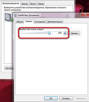
Disable everything sound effects and equalizers, open the speaker properties and set the volume level to 100%.
Open the program, click “Options”, select “Frequency” in “Tone Interval”, and set the step to 1Hz.

Close “Options”, set the volume level to 100%, set the initial frequency to 10Hz and press “Play”. Using the “+” button, we begin to smoothly, in 1Hz steps, increase the generator frequency to 500Hz.

At the same time, we look at the voltage value on the voltmeter. If the maximum amplitude difference is within 2 dB (1.259 times), then such sound card Suitable for measuring speaker parameters. For example, I have maximum value was 624 mV, and the minimum was 568 mV, 624/568 = 1.09859 (0.4 dB), which is quite acceptable.
1.1.2. Let's move on to the long-awaited Thiel-Small parameters. The minimum parameters by which you can calculate and design an acoustic design (in this case, a subwoofer) are:
- Resonance frequency (Fs),
- Total electromechanical quality factor (Qts),
- Equivalent volume (Vas).
For a more professional calculation, you will need even more parameters, such as mechanical quality factor (Qms), electrical quality factor (Qes), sensitivity (SPL), etc.
1.1.2.1. Determination of the resonant frequency (Fs) of a loudspeaker.
Let's put together this diagram.


The speaker should be in free space as far as possible from the walls, floor and ceiling (I hung it from a chandelier). Open the NCH Tone Generator program again, set the volume as described above, set the initial frequency to 10Hz and begin to smoothly increase the frequency in 1Hz steps. In this case, again, we look at the value of the voltmeter, which will first increase, reach the maximum point (Umax) at the natural resonance frequency (Fs), and begin to decrease to the minimum point (Umin). At further increase frequency, the voltage will gradually increase. The graph of voltage (active resistance of the speaker) versus signal frequency looks like this.

The frequency at which the voltmeter value is maximum is the approximate resonant frequency (in 1Hz steps). To determine the exact resonant frequency, you need to change the frequency in the region of the approximate resonant frequency in steps of not 1 Hz, but 0.05 Hz (accuracy 0.05 Hz). We write down the resonant frequency (Fs), the minimum value of the voltmeter (Umin), the value of the voltmeter at the resonant frequency (Umax) (later they will be useful for calculating the following parameters).
1.1.2.2.
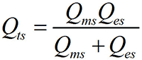
Determination of the total electromechanical quality factor (Qts) of a loudspeaker.
We find UF1,F2 using the following formula.
![]()
By changing the frequency, we achieve the voltmeter values corresponding to the voltage UF1, F2. There will be two frequencies. One is lower than the resonant frequency (F1), the other is higher (F2).

You can check the correctness of the calculations using this formula.

If the difference between Fs’ and Fs does not exceed 1 Hz, then you can safely continue measurements. If not, then you need to do everything all over again. We find the mechanical quality factor (Qms) using this formula.

The electrical quality factor (Qes) is found using this formula.

Finally, we determine the total electromechanical quality factor (Qts) using this formula.
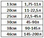
1.1.2.3. Determination of the equivalent volume (Vas) of a loudspeaker.
To determine the exact equivalent volume, we will need a pre-fabricated, durable, sealed bass reflex box with a hole for our speaker.

The volume of the box depends on the diameter of the speaker, and is selected according to this table.
We fix the speaker to the box and connect it to the circuit described above (Fig. 9). Again, open the NCH Tone Generator program, set the initial frequency to 10Hz and using the “+” button, we begin to smoothly, in 1Hz steps, increase the generator frequency to 500Hz. At the same time, we look at the voltmeter value, which will again begin to increase to the frequency FL, then decrease, reaching a minimum point at the bass reflex tuning frequency (Fb), increase again and reach the maximum point at the frequency FH, then decrease and slowly increase again. The graph of voltage versus signal frequency has the shape of a Bactrian camel.

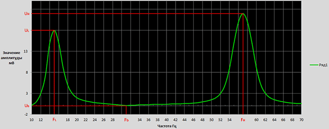

And finally, we find the equivalent volume (Vas) using this formula (where Vb is the volume of the box with the bass reflex).

We repeat all our measurements 3-5 times and take the arithmetic average of all parameters. For example, if we received the Fs values respectively 30.45Hz 30.75Hz 30.55Hz 30.6Hz 30.8Hz, then we take (30.45+30.75+30.55+30.6+30.8)/5= 30.63Hz.
As a result of all my measurements, I received the following parameters for my speaker:
- Fs=30.75 Hz
- Qts=0.365
- Vas=112.9≈113 l
1.2.Modeling and calculation of the subwoofer body (box) using the JBL Speakershop program.
There are several options for acoustic designs, of which the following options are the most common.
- Vented box with bass reflex,
- Band-pass 4th, 6th and 8th order,
- Passive radiator - box with a passive radiator,
- Closed box - closed box.

The type of acoustic design is selected based on the Thiel-Small parameters of the loudspeaker. If Fs/Qts<50, то такой громкоговоритель можно использовать исключительно в закрытом оформлении, если Fs/Qts>100, then exclusively in Vented box or Band-pass or Closed box. If 50
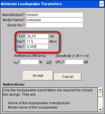
First, download and install the program. This program is written for Windows XP and does not work on Windows 7. To make the program work on Windows 7, you need to download and install virtual machine Windows Virtual PC-XP Mode (you can download it from the official Microsoft website), and run the JBL Speakershop installation through it. You also need to open JBL Speakershop through a virtual machine. After opening the program we see this interface.

Click “Loudspeaker” and select “Parameters--minimum”, in open window We write, respectively, the value of the resonant frequency (Fs), the value of the equivalent volume (Vas), the value of the total electromechanical quality factor (Qts) and click “Accept”.
In this case, the program will offer two optimal (with the most even frequency response) options, one in a closed design (Closed box), the other in a Vented box (box with a bass reflex). Click “plot” (both in the Vented box area and in the Closed box area) and look at the frequency response graph. We choose the design whose frequency response most suits our requirements.

In my case this is a Vented box, because low frequencies ah (20-50Hz) the Closed box has a much greater amplitude decay than the Vented box (Figure above).
If the optimal volume of the box suits you, then you can build a box with that volume and enjoy the sound of the subwoofer. If not (if the volumes are too large), then you need to set your volume (the closer to the optimal volume, the better) and calculate the optimal tuning frequency of the bass reflex.

To do this, in the Vented box area, click “Custom”, in the window that opens, write your box volume, click “Optimum Fb” (in this case, the program will calculate the optimal tuning frequency of the bass reflex, at which the frequency response of the acoustic design will be the most linear) and then “Accept”.

Click “Box” and select “Vent...”, in the window that opens, in the “Custom” area, write the diameter of the pipe (Dv), which we will use as a bass reflex. If we use two bass reflexes, then we put a dot on “Area” and write the total cross-sectional area of the pipes.


Click “Accept” and in the “Custom” area on the Lv line the length of the bass reflex pipe will appear. Now that we know the internal volume of the box, the diameter and length of the bass reflex pipe, we can safely move on to designing the acoustic design, but if you really want to know the optimal aspect ratio of the box, you can click “Box” and select “Dimensions...”.

1.3.Design of the subwoofer housing (box)
To obtain high-quality sound, it is necessary not only to correctly calculate, but also to carefully manufacture the acoustic design housing. After determining the internal volume of the box, the length and diameter of the bass reflex pipe, you can safely proceed to the manufacture of the subwoofer enclosure. The material of the box must be strong and rigid enough. The most suitable material for high-power acoustic cabinets is twenty-millimeter MDF. The walls of the box are attached to each other with self-tapping screws, and the gaps between them are smeared with sealant or silicone. After making the box, holes are made for the handles, and the finishing of the outer surface begins. All unevenness will be smoothed out using putty or epoxy resin (I add a little PVA glue to the putty, which prevents cracks from appearing over time and reduces the level of vibrations). After the putty has dried, the surfaces must be sanded until perfectly smooth walls are obtained. The finished box can be either painted or covered with self-adhesive decorative film, or simply glued with thick fabric. From the inside, a sound-absorbing material consisting of cotton wool and gauze is glued to the walls of the box (in my case I glued batting). As a bass reflex, you can use a plastic sewer pipe or a paper rod from different rolls, as well as a ready-made bass reflex that can be bought at almost any music store.
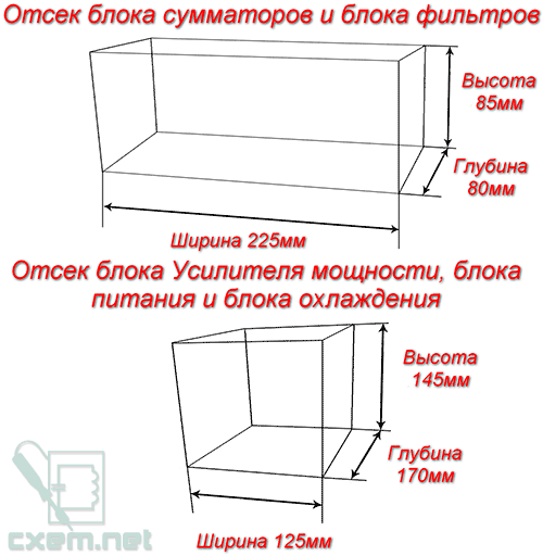
The active subwoofer housing consists of two compartments. The first compartment houses the loudspeaker itself, and the second contains the entire electrical part (signal conditioner, amplifier, power supply......). In my case, I placed the adder unit and filter unit in a separate compartment from the power amplifier unit, power supply and cooling unit. From the inside, I glued foil to the walls of the adder block and filter block compartment, which I connected to ground (GND). The foil prevents exposure to external fields and reduces noise levels.


If you use my printed circuit boards, these compartments should have the following dimensions.


2. Electrical part of the active subwoofer
Let's move on to the electrical part of the active subwoofer. General scheme and the operating principle of the device is represented by this diagram.
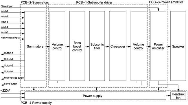
The device consists of four blocks assembled on separate printed circuit boards.
- Block of adders (Summators),
- Filter block (Subwoofer driver),
- Power amplifier block,
- Power supply and cooling unit (Heatsink fun).
At first sound signal enters the adder block (Summators), where the signals of the right and left channels are summed. Then it goes to the filter block (Subwoofer driver), where the subwoofer signal is formed, which includes a volume control, subsonic filter (infra low-pass filter), bass booster (increasing the volume at a certain frequency) and Crossover (low-pass filter). After formation, the signal enters the power amplifier block, and then into the loudspeaker.
Let's discuss these blocks separately.
2.1. Block of adders (Summators)
2.1.1.Scheme
First, let's look at the adder circuit shown in the figure below.

Beep with external devices(computer, CD player……..) enters the adder block, which has 6 stereo inputs. 5 of them are ordinary linear inputs, differing from each other only in the type of connector. And the sixth is a high-voltage input to which you can connect the speaker output (for example, music Center or car radio that do not have line output). Each input has a separate operational amplifier combiner that biases the signals of the right and left channels, which prevents the audio signal from one external device from entering another, while making it possible to simultaneously connect several external devices to the subwoofer. There are also outputs (5 outputs, the 6th simply didn’t fit on the board, so I didn’t install it), which make it possible to supply the same signal that goes into the subwoofer to the input of a wideband stereo system. This is very convenient when the sound source has only one output.


2.1.2.Components
TL074 (5 pcs.) were used as operational amplifiers. Resistors are rated for power of 0.25W or higher (resistance ratings are shown in the diagram). All electrolytic capacitors have a voltage rating of 25 Volts or higher (capacitance ratings are shown in the diagram). As non-polar capacitors, you can use ceramic or film capacitors (preferably film), but if you really want to, you can use special audio capacitors (capacitors designed for use in high-quality audio systems). Chokes in the power supply circuit of operational amplifiers are designed to suppress “noise” coming from the power supply. Coils L1-L4 contain 20 turns wound with copper wire with a diameter of 0.7 mm on a gel pen rod (3 mm). Also used are RCA, 3.5mm audio jack, 6.35mm audio jack, XLR, WP-8 connectors.

2.1.3.PCB


The printed circuit board is made using . After soldering the parts, the printed circuit board should be coated to avoid oxidation of the copper.
2.1.4.Photo finished block adders


The adder unit is powered from a bipolar power supply with a voltage of ±12V. The input impedance is 33kOhm.
2.2.Filter block (Subwoofer driver)
2.2.1.Scheme
Consider the subwoofer driver circuit shown in the figure below.

The summed signal from the adder block enters the filter block, which consists of the following parts:
- Volume regulator,
- Infra-low frequency filter (subsonic filter),
- Bass booster of a certain frequency (bass booster),
- Low pass filter (crossover).
Volume control occurs at two levels. The first is when the signal enters the filter block, which reduces the level of its own “noise” of the adder block, the second is when the signal outputs from the filter block, which reduces the level of its own “noise” of the filter block. The volume is adjusted using variable resistor VR3. After the first level of volume control, the signal enters the so-called “bass booster,” which is a device that increases the amplitude of signals of a certain frequency. That is, if the bass booster tuning frequency is set to, for example, 44Hz, and the gain level is 14dB, then the frequency response looks like this ( Row1).

Row2- tuning frequency=44Hz, gain level=9dB,
Row3- tuning frequency=44Hz, gain level=2dB,
Row4- tuning frequency=33Hz, gain level=3dB,
Row5- tuning frequency=61Hz, gain level=6dB.
The bass booster tuning frequency is set using variable resistor VR5 (within 25...125Hz), and the gain level with resistor VR4 (within 0...+14dB). After the bass booster, the signal enters the subsonic filter, which is a filter that cuts off unwanted, ultra-low signals that are no longer audible to humans, but can greatly overload the amplifier, thereby reducing the actual output power of the system. The filter cutoff frequency is adjusted using variable resistor VR2 within the range of 10...80Hz. If, for example, the cutoff frequency is inserted at 25Hz, then the frequency response has the following form.

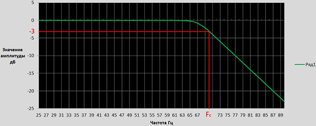
After the infra-low-pass filter, the signal enters the low-pass filter (crossover), which cuts off the upper frequencies (mid + high) that are unnecessary for the subwoofer. The cutoff frequency is adjusted using a variable resistor VR1 within the range of 30…250Hz. The attenuation slope is 12 dB/octave. The frequency response looks like this (at a cutoff frequency of 70Hz).
2.2.2.Components
TL074 (2 pcs.), TL072 (1 pc.) and NE5532 (1 pc.) were used as operational amplifiers. Resistors are rated for power of 0.25W or higher (resistance ratings are shown in the diagram). All electrolytic capacitors have a voltage rating of 25 Volts or higher (capacitance ratings are shown in the diagram). Ceramic or film capacitors (preferably film) can be used as non-polar capacitors. Chokes in the power supply circuit of operational amplifiers are designed to suppress “noise” coming from the power supply. Three double (50kOhm-2pcs., 20kOhm-1pc.) and two quadruple variable (50kOhm-6pcs.) resistors were also used. As quads variable resistors you can use two double ones.
2.2.3.PCB

PCB files in *.lay and *.pdf formats can be downloaded at the end of the article.
2.2.4.Photo of the finished filter block


The filter unit is powered from a bipolar power supply with a voltage of ±12V.
2.3.Power amplifier block.
2.3.1.Scheme
The power amplifier is an Anthony Holton amplifier with field-effect transistors in the output stage. There are a lot of articles describing the operating principle, assembly and configuration of the amplifier on the Internet. Therefore, I will limit myself to attaching the schematic and my version of the printed circuit board.

2.3.2.PCB
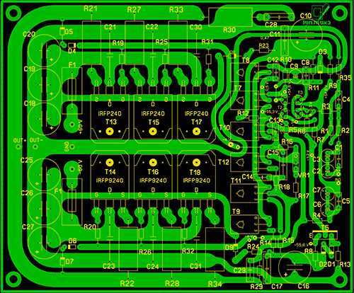


PCB files in *.lay and *.pdf formats can be downloaded at the end of the article. The power amplifier unit is powered from a bipolar power supply with a voltage of ±50…63V. The output power of the amplifier depends on the supply voltage and the number of pairs of field-effect transistors (IRFP240+IRFP9240) in the output stage.
2.4. Power supply and cooling unit (Power supply)
2.4.1.Scheme
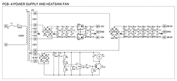
2.4.2.Components
As a power transformer, you can use both ready-made and homemade transformer power approximately 200W. The voltages of the secondary windings are shown in the diagram.


The Br2 diode bridge is designed for a current of 25A. Capacitors C1…C12,C29…C31 must have a rated voltage of 25V. Capacitors C13...C28 must have a rated voltage of 63V (for supply voltages below 60V), or 100V (for supply voltages above 60V). It is better to use film capacitors as non-polar capacitors. All resistors are rated for 0.25W power. Thermistor R5 is coated with thermal paste and attached to the amplifier's heatsink. The operating voltage of the fan is 12V.
2.4.3.PCB

PCB files in *.lay and *.pdf formats can be downloaded at the end of the article.
3.The final stage of subwoofer assembly


List of radioelements
| Designation | Type | Denomination | Quantity | Note | Shop | My notepad | |
|---|---|---|---|---|---|---|---|
| U1-U5 | Operational amplifier | TL074 | 5 | To notepad | |||
| C1-C4, C15, C16, C25-C27, C29, C39-C42 | 10 µF | 14 | To notepad | ||||
| C5-C10, C23, C24, C28, C30, C35-C38 | Capacitor | 33 pF | 14 | To notepad | |||
| C11-C14, C19-C22, C31-C34 | Capacitor | 0.1 µF | 12 | To notepad | |||
| C17, C18 | Electrolytic capacitor | 470 µF | 2 | To notepad | |||
| R1, R2 | Resistor | 390 Ohm | 2 | To notepad | |||
| R3, R12 | Resistor | 15 kOhm | 2 | To notepad | |||
| R4, R16-R18 | Resistor | 20 kOhm | 4 | To notepad | |||
| R5, R13-R15 | Resistor | 13 kOhm | 4 | To notepad | |||
| R6, R10, R23, R24, R31, R33, R40, R41, R46, R47 | Resistor | 68 kOhm | 10 | To notepad | |||
| R7, R11, R21, R22, R32, R34, R37, R38, R45, R48 | Resistor | 22 kOhm | 10 | To notepad | |||
| R8, R9, R25, R26, R29, R30, R39, R42, R49, R50 | Resistor | 10 kOhm | 10 | To notepad | |||
| R19, R20, R27, R28, R35, R36, R43, R44 | Resistor | 22 Ohm | 8 | To notepad | |||
| L1-L4 | Inductor | 20x3mm | 4 | 20 turns, wire 0.7mm, frame 3mm | To notepad | ||
| L5-L13 | Inductor | 100 mH | 10 | To notepad | |||
| Filter block | |||||||
| U1 | Operational amplifier | TL072 | 1 | To notepad | |||
| U2, U4 | Operational amplifier | TL074 | 2 | To notepad | |||
| U3 | Operational amplifier | NE5532 | 1 | To notepad | |||
| C1-C5, C7-C10, C15-C17, C20, C23 | Capacitor | 0.1 µF | 14 | To notepad | |||
| C6 | Capacitor | 15 nF | 1 | To notepad | |||
| C11-C14 | Capacitor | 0.33 µF | 4 | To notepad | |||
| C21, C22 | Capacitor | 82 nF | 2 | To notepad | |||
| VR1-VR3, VR5 | Variable resistor | 50 kOhm | 4 | To notepad | |||
| VR4 | Variable resistor | 20 kOhm | 1 | To notepad | |||
| R1, R3, R4, R6 | Resistor | 6.8 kOhm | 4 | To notepad | |||
| R2, R10, R11, R13, R14 | Resistor | 4.7 kOhm | 5 | To notepad | |||
| R5, R8 | Resistor | 10 kOhm | 2 | To notepad | |||
| R7, R9 | Resistor | 18 kOhm | 2 | To notepad | |||
| R12, R15-R17, R20, R22, R26, R27 | Resistor | 2 kOhm | 8 | To notepad | |||
| R18, R25 | Resistor | 3.6 kOhm | 2 | To notepad | |||
| R19, R21 | Resistor | 1.5 kOhm | 2 | To notepad | |||
| R23, R24, R30, R31, R33 | Resistor | 20 kOhm | 5 | To notepad | |||
| R28 | Resistor | 13 kOhm | 1 | To notepad | |||
| R29 | Resistor | 36 kOhm | 1 | To notepad | |||
| R32 | Resistor | 75 kOhm | 1 | To notepad | |||
| R34, R35 | Resistor | 15 kOhm | 2 | To notepad | |||
| L1-L8 | Inductor | 100 mH | 1 | To notepad | |||
| Power amplifier block | |||||||
| T1-T4 | Bipolar transistor | 2N5551 | 4 | To notepad | |||
| T5, T9, T11, T12 | Bipolar transistor | MJE340 | 4 | To notepad | |||
| T7, T8, T10 | Bipolar transistor | MJE350 | 3 | To notepad | |||
| T13, T15, T17 | MOSFET transistor | IRFP240 | 3 | To notepad | |||
| T14, T16, T18 | MOSFET transistor | IRFP9240 | 3 | To notepad | |||
| D1, D2, D5, D7 | Rectifier diode | 1N4148 | 4 | To notepad | |||
| D3, D4, D6 | Zener diode | 1N4742 | 3 | To notepad | |||
| D8, D9 | Rectifier diode | 1N4007 | 2 | ||||
Here specifications TDA1562 chips:
Supply voltage – 8..18V;
Peak output current – 10A;
Current in rest mode – 0.15A;
Load resistance – 4 Ohms;
Output power, at harmonic distortion
-0.03% - 1 W
-0.06% - 20 W
-0.5% - 55 W
-10% - 70 W
Voltage gain – 26 dB
Reproducible frequency range – 16…20000 Hz
Input impedance – 10 kOhm
The price of TDA1562 is approximately 6.
This microcircuit is equipped with a voltage boost, the essence of which is that when playing sound signals, high output power is required for a short period of time, and the rest of the time the output power remains low. Therefore, as long as the output power does not exceed 18W, the device functions as a regular ULF powered by a 12V source. When the output power exceeds 18 W, the internal supply voltage is briefly increased using a converter that includes boost capacitors. This solution allows you to obtain higher peak power at the load with standard power supply on-board network auto - 12V.

By closing the contacts, the microcircuit is transferred from standby mode to operating mode and vice versa. It is not recommended to connect the amplifier to subwoofers with built-in filters containing significant capacitances. The TDA1562 chip is quite sensitive to supply voltage, so do not apply more than 18V to it. develops an output power of 70 W at a 4 Ohm load when powered from a unipolar 15 V source.

To install the microcircuit, use thick wires, since current consumption is up to 10 amperes. This also applies to the wires going to the subwoofer speaker, because even a slight increase in line resistance will lead to power loss.

The amplifier chip of a homemade subwoofer must be installed on a heat sink with an area of at least 500 cm2. Can be used as a radiator metal case or car chassis. As an option, you can use forced airflow of the microcircuit with a 12-volt cooler from.

We make the subwoofer housing from fiberboard of sufficient thickness so that there is no rattling or overtones. We cover the outside with soft cloth to absorb vibration. We use standard tulips and spring pedals as connectors.


Two are used to indicate subwoofer modes. Green indicates the supply of 12V supply voltage to the circuit, and red indicates overloads and protection activation in the TDA1562


The 12V power supply must be screwed in place to improve contact and reduce losses. Tests of the finished subwoofer have shown that the sound is no worse than branded subs in the mid-price range, and it is quite possible to assemble a good bass system in a car with your own hands in just 35 and two evenings. Material sent by - in_sane
Discuss the article HOMEMADE SUBWOOFER
A subwoofer is an element of an acoustic system that reproduces the sound of audio tracks at the lowest frequencies. Having a good subwoofer is a music lover’s dream, because everyone loves high-quality sound of music inside the car. However, such a device is not cheap. However, most car owners can calculate the subwoofer box and make it themselves in order to avoid unnecessary expenses on a factory model.
How to choose speakers for your subwoofer
Subwoofers are used in cars to improve the sound of music at low frequencies. For regular listening to melodies or radio broadcasts, the standard audio system in the car is quite sufficient, but connoisseurs of loud and clear sound at low frequencies prefer to place a subwoofer in the cabin.
When selecting speakers for a future product, the car owner learns that they can be round or oval in shape and size. Typically (based on the dimensions of the car interior), round speakers with a diameter of 10, 13 or 16 cm, as well as oval ones with a length of 15x23 cm are selected. Accordingly, the larger the diameter of the speaker, the better the sound will be reproduced at low frequencies.
How to Know Which Car Speakers Are Right for You
Before making a subwoofer for your car yourself, you need to clarify several basic points:
- The shape of the speakers does not affect the sound quality of music in the car;
- The depth and richness of the sound is affected only by the size of the speaker;
- You need to think carefully about the exact shape and size of the speakers so that the subwoofer looks appropriate in the cabin.
Design is not of paramount importance, so when choosing a speaker, its technical characteristics are a priority
Designing a homemade subwoofer
Car subwoofers are installed in the luggage compartment or on the rear parcel shelf, which is why this system is called rear.
The most important point in manufacturing is determining its size and design. Depending on the tasks assigned, the design can have a variety of variations.
Types of subwoofers
There are only two main types of subwoofers. If we talk about the relationship to an audio power amplifier, then they are conventionally divided into:
- active. They already have a built-in amplifier and crossover, which provide high sound quality and remove high frequencies from the sound. An active subwoofer receives signals from any source with which it has a connection;
- passive. The device is not equipped with additional amplification elements, so it is connected to the main audio system of the cabin. The only drawback of a passive subwoofer is that it seriously loads all the channels of the system, and therefore the sound quality decreases.
Active subwoofers do not load the standard cabin audio system, so they have better sound quality
Where to install: in the trunk or under the seat
If active subwoofer can be placed almost anywhere, the location of the passive device will directly determine the purity and power of its sound at low frequencies.
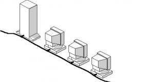
- Depending on the preferences of the car owner and the availability of free space in different types of cars, several installation locations are offered:
- in the center in front is the optimal position for communication with the front speakers, which will ensure almost ideal sound of tracks in the cabin. However, most cars don't have room in the front to accommodate any large devices, so a center front location is more suitable for minibuses;
- in the trunk, with the speaker directed forward - one of the most popular ways to place a subwoofer among drivers. Suitable for all types of vehicles;
- in the trunk, with the speaker directed backwards - more suitable for a car in a hatchback body, since the sound wave does not encounter obstacles in its path. The location in the trunk back is unacceptable for cars in a sedan or coupe, since the sound will be greatly deformed due to the specific design of the luggage compartment;
- on the floor under the seat is another option, which, however, is not widely popular among drivers. Due to the fact that the subwoofer is located flush with the floor, and the housing is located under the seat, the sound encounters many obstacles in its path; on the back shelf is one of best options
placing a subwoofer in all types of cars. The main condition is that the shelf must be wide and strong enough to withstand low-frequency bass.
Photo gallery: main places to place the device in a car
The program algorithm will take into account all your wishes and calculate the volume and other parameters of the case quickly and correctly
What to make a box from A subwoofer box is more than just a box that houses a speaker. The box must comply with many dynamic laws of acoustics in order for the sound to be truly rich and clear. For the manufacture of boxes will require different materials, and the manufacturing methods will in many ways be different from one another.
How to build a box for a bass reflex subwoofer
The standard version of a homemade subwoofer is a bass reflex. This is the simplest type of subwoofer; moreover, its box is good because a special bass reflex tube allows you to reproduce low frequencies that are practically not perceived by the human ear. And the design of the box is quite simple, which makes its production accessible to almost everyone.
Required tools:
- sound insulation;
- wood screws 50 mm long;
- drill;
- screwdriver;
- electric jigsaw;
- liquid Nails;
- sealant;
- PVA glue;
- carpet
The housing for housing a bass reflex subwoofer should be as durable as possible and not leak sound waves. Multilayer plywood or chipboard is perfect for these purposes. High Quality. The best option- take a plywood sheet 30 mm thick.
To make the case you need to follow this plan:
- Prepare parts of the body: front, back, two sides, bottom and top in accordance with your calculations or parameters derived by programs.
- To fit the speaker size (for example, diameter 160 mm), cut a hole in the front part of the housing blank.
- Above the hole for the speaker you will also need to cut a slot for the bass reflex tube and screw the bass reflex compartment to it.
- After two holes are made on the front panel, you need to glue all the side parts of the box together and then screw them to each other with self-tapping screws.
- In this case, it is especially important to tighten each screw until it stops, since empty spaces between the panels will seriously distort the sound of the speaker.
- Next, you will need to cut a small hole for the wires on the back of the case.
- Before connecting all parts of the case, we insert the speaker.
- Next, it is necessary to carry out the interior finishing of the case: for this, all joints and cracks need to be coated with resin or sealant to improve the sealing, after which soundproofing fabric is glued to all side panels.
- After completing the interior decoration, you need to move on to the exterior: the body is covered with carapet fabric, and the fabric should also cover the slot for the bass reflex. Karapet can be tensioned using regular epoxy or a furniture stapler.
Once the speaker is secured, wires are pulled from it through the hole and connected to the car's sound system.
Photo gallery: how to assemble a compact box with a bass reflex
You can connect the subwoofer yourself, based on the parameters of this circuit
Before starting work, make sure that the vehicle battery is disconnected. This is a safety measure that will not only avoid damage to the speaker system, but can also preserve the health and performance of parts of the human body.
Video: connecting and setting up a subwoofer
Independent design, manufacture and connection of subwoofers in a car is available to almost every driver. The key to success will be both a competent calculation of the dimensions and volume of the product, and careful assembly of the case. At the same time, the car enthusiast can independently select the desired size of speakers in order to create in the cabin the low-frequency sound that suits him most.
The thing that we will now talk about, as is clear from the title of the article, is homemade amplifier for a subwoofer, popularly called “Sub”. The device has an active low-pass filter built on operational amplifiers and a combiner that provides signal input from the stereo output.
Since the signal for the circuit is taken from the outputs on Acustic systems, there is no need to interfere with a running amplifier. Receiving the signal from the speakers has another advantage, namely, it allows you to maintain a constant volume ratio of the subwoofer to the stereo system.
Naturally, the subwoofer channel gain can be adjusted using a potentiometer. After filtering high frequencies and highlighting low frequencies (20-150 Hz), the audio signal is amplified using the TDA2030 or TDA2040, TDA2050 microcircuit. This allows you to customize the bass output to your liking. Any woofer with more than 50 watts of power per subwoofer will work successfully in this project.
Filter circuit with UMZCH subwoofer
 Schematic diagram of low-pass filter and UMZF subwoofer
 Description of the operation of the amplifier circuit
The stereo signal is fed to the In connector via C1 (100nF) and R1 (2.2M) on the first channel and C2 (100nF) and R2 (2.2M) on the other channel. It is then fed to the input of op-amp U1A (TL074). Potentiometer P1 (220k) operating in circuit feedback amplifier U1A, the gain of the entire system is adjusted. Next, the signal is fed to a second-order filter with elements U1B (TL074), R3 (68k), R4 (150k), C3 (22nF) and C4 (4.7 nF), which works as a Butterworth filter. Through circuit C5 (220nF), R5 (100k), the signal is supplied to repeater U1C, and then through C6 (10uF) to the input of amplifier U2 (TDA2030).
Capacitor C6 ensures separation of the DC component of the preamplifier signal from the power amplifier. Resistors R7 (100k), R8 (100k) and R9 (100k) serve to polarize the amplifier input, and capacitor C7 (22uF) filters the offset voltage. Elements R10 (4.7 k), R11 (150 k) and C8 (2.2 uF) operate in a negative feedback loop and have the task of forming the spectral characteristics of the amplifier. Resistor R12 (1R) together with capacitor C9 (100nF) form the output characteristic. Capacitor C10 (2200uF) prevents the passage direct current through the speaker and, together with the speaker resistance, determines the lower cutoff frequency the entire amplifier.
Protection diodes D1 (1N4007) and D2 (1N4007) prevent voltage surges that may occur in the speaker coil. The supply voltage, in the range of 18-30 V, is supplied to the Zas connector, capacitor C11 (1000 - 4700uF) is the main filter capacitor (do not skimp on its capacity). Regulator U3 (78L15) together with capacitors C12 (100nF), C15 (100uF) and C16 (100nF) provides a 15 V supply voltage to the U1 chip. Elements R13 (10k), R14 (10k) and capacitors C13 (100uF), C14 (100nF) form a voltage divider for operational amplifiers, forming half of the supply voltage.
Subwoofer assembly
The entire system is soldered to . Installation should begin by soldering two jumpers. The installation order of the remaining elements is any. At the very end, capacitor C11 should be soldered in because it must be installed lying down (the legs need to be bent accordingly).
 Printed circuit board for the device
 The input signal must be connected to the In connector using twisted wires (twisted pair). The U2 chip must be equipped with a large radiator.
The circuit should be powered from a transformer through a diode bridge rectifier; the filter capacitor is already on the board. The transformer must have a secondary voltage in the range of 16 - 20 V, but so that after rectification it does not exceed 30 V. A subwoofer should be connected to the output with good parameters- A lot depends on the head.